GIGABYTE Z97X-SOC Force Motherboard Review
GIGABYTE Z97X-SOC Force Motherboard Layout
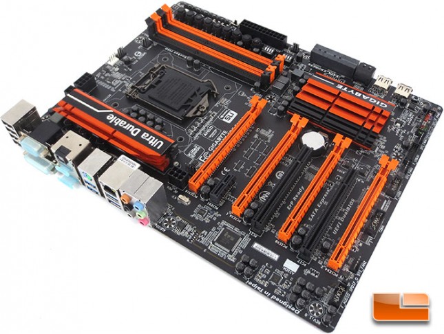
Orange isn’t my first choice when it comes to motherboards, or computer components in general. Though I’ll admit that the GIGABYTE Z97X-SOC Force isn’t to bad when it comes to the overall look, actually I kinda like it. I’ve said it before and I’ll continue to say it, performance will always trump the aesthetics any day of the week.
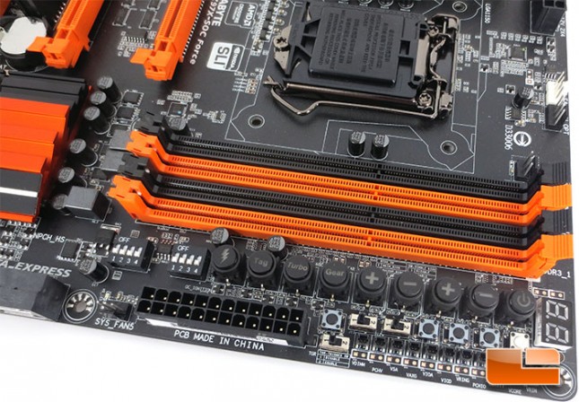
This particular corner of the GIGABYTE Z97X-SOC Force is pretty well packed with features, probably the most of any section of the board. The GIGABYTE Z97X-OC Force packs the usual four DIMM slots here, each of these will support an 8Gb module for a maximum of 32Gb and up to 3300MHz (O.C.). As with all of the Intel Z97 motherboards out there the Z97X-SOC Force will support memory in a dual channel memory architecture. At the upper right hand corner of the DIMM slots there is three fan headers. The top most pair of the three are the CPU Fan and secondary CPU fan headers, both of these are four pin fan headers. The third right at the DIMM slots is a 3pin fan header that is ideal for a memory fan header like the Corsair AirFlow II memory fans.
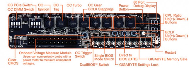
The OC Touch panel on the GIGABYTE Z97X-SOC Force is pretty complex at first glimpse, though it’s pretty well laid out once you start tinkering with it. Along the bottom edge to the right of the 24 pin motherboard power is the OC Trigger switch and the Onboard Voltage measuring points. Just above those points there is a Clear CMOS button, DualBIOS switch, Single BIOS mode switch, GIGABYTE Settings lock, GIGABYTE Memory Safe and the Direct to BIOS buttons. Along the right edge of the OC Touch panel is the Debug Display. Moving left from there we have the power buttin, CPU ratio up and down buttons, BCLD up and down buttons, OC Gear BCLD steppings, OC Turbo, OC Tag, OC Ignition, OC PCIe Switch, OC DIMM switch.
This section of the GIGABYTE Z97X-SOC Force is a little less busy than the previous corner was, though no less important. Along the left edge there is the pinout for the front panel, a 4pin system fan header, Internal SuperSpeed USB 3.0 header, a second 4pin system fan header, followed by a pair of internal USB 2.0 headers.
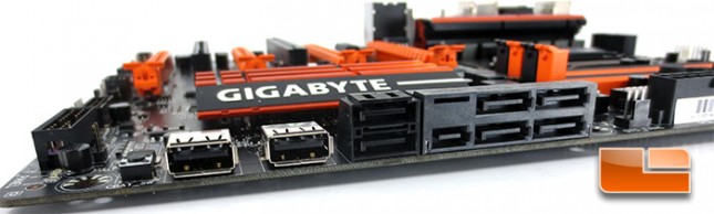
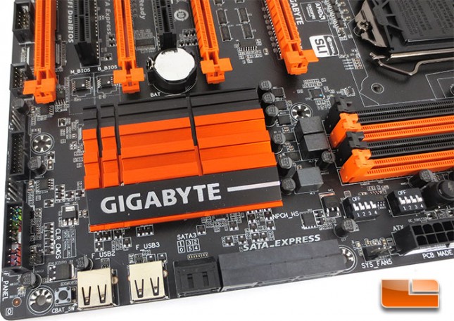
The edge of the GIGABYTE Z97X-SOC Force motherboard features six SATA III 6Gbps ports, though a pair of them can be utilized for the latest in connectivity, SATA Express. To the left of the SATA ports is a pair of USB 2.0 ports, there’s a number of ways these can be utilized but I’ll let you use your imagination. Though mostly it’s used for extreme overclocking situations when this is easier to access than the rear I/O panel at times. From these USB 2.0 ports you can flash the BIOS, save BIOS OC profiles, load OC profiles, or simply transfer files to the system prior to installing it into a chassis.
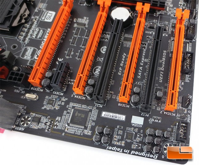
Continuing along the right edge of the GIGABYTE Z97X-SOC Force where we left off above, there is another 4pin system fan header, SPDIF out, and the front panel audio header. Just a hair above the ‘in’ we can find the Realtek ALC1150 High Definition audio codec and it is surrounded by the various capacitors as well as the line that physically separates the audio components from the remainder of the board. The GIGABYTE Z97X-SOC Force has four PCIe x16 slots and will support up to 4-way AMD CrossFireX and 2-way NVIDIA SLI. If you’re wondering why the GIGABYTE Z97X-SOC Force will only support 2-Way SLI, when more than two cards are installed the PCIe x8 slots will run at x4 which isn’t supported by NVIDA SLI. One of the reasons for this is that GIGABYTE left out the PLX chip on this board, it’s known that the PLX chip can increase the latency and since this is a board targeted for extreme overclocking, GIGABYTE didn’t want to add anything that would hinder performance. If you’re looking to run a quad SLI setup, take a look at the GIGABYTE Gaming series of boards like the GIGABYTE Z97X-Gaming G1 Wi-Fi BK. Going almost unnoticed in this picture, there is a 6pin PCIe power plug next to the PCIe 16 slot, this will supply additional power to the PCIe x16 slots when running multiple cards.
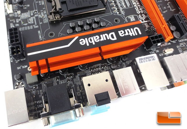
Looking at the final corner of the GIGABYTE Z97X-SOC Force from the top down, there aren’t many discernible features. Though one that stands out is the 4pin CPU power on the left hand side. The 4pin CPU power is in addition to the typical 8pin CPU power, you don’t need to use this for day to day operations, but if you’re doing some extreme overclocking with LN2 or Liquid Helium it certainly couldn’t hurt.
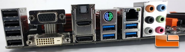
The I/O panel of the GIGABYTE Z97X-SOC Force isn’t to far out of the ordinary. The Z97X-SOC Force is equipped with four USB 2.0 ports, four SuperSpeed USB 3.0 ports, DVI-D, D-Sub, HDMI 1.4a, DisplayPort, Optical SPDIF, Gigabit LAN, 6 3.5mm audio jacks. The Z97X-SOC Force also has a single PS/2 port that can be used for either a keyboard or a mouse.
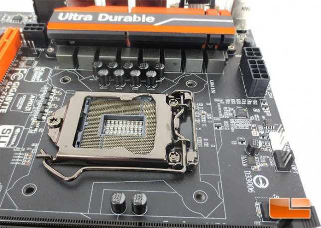
The area surrounding the Intel LGA1150 socket is kept pretty bare when you look at some of the other top boards out there. The Z97X-SOC Force features 15u gold plated LGA1150 socket. This isn’t only for some sharp look, it helps to improve the conductivity of the pins and improve the reliability and longevity of the socket.