BIOSTAR Gaming Z170X ATX Motherboard Review
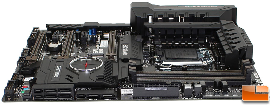
BIOSTAR Gaming Z170X Layout
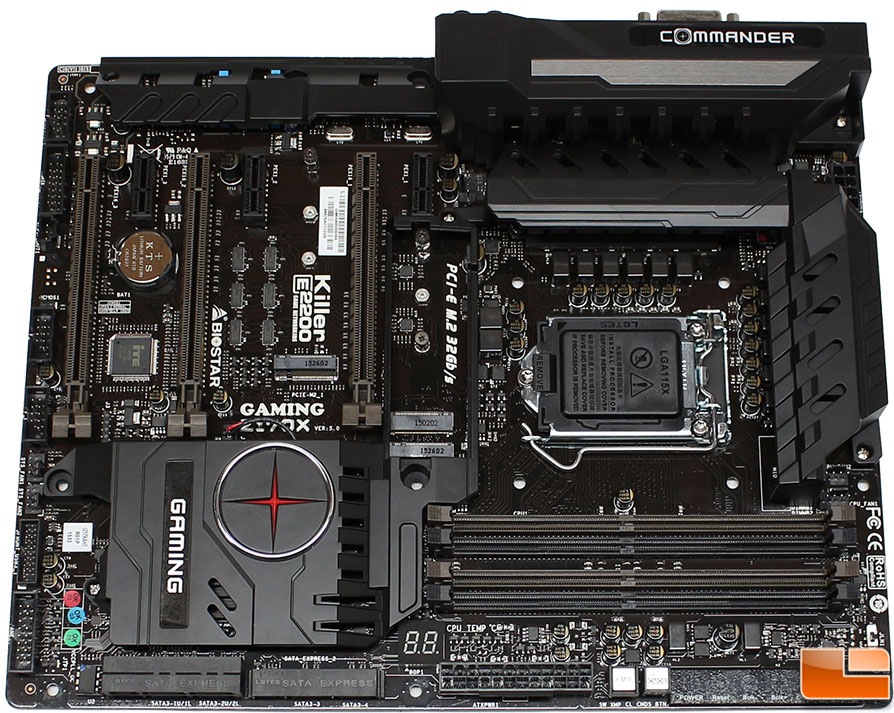
Overall, the color scheme of the BIOSTAR Gaming Z170X is Brown and black, providing a very militaristic look. The only splash of color on the motherboard comes from the Z170 chipset heatsink, which has the BIOSTAR Gaming crosshair logo on it, which lights up in red once the motherboard is powered up. The two large sections of the heatsinks are covered with a plastic shielding, which again leans towards a militaristic vibe.
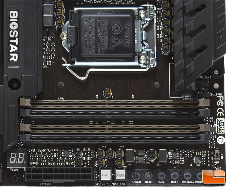
Starting in the lower right corner of the motherboard, the biggest feature we find here is the four DDR4 memory slots. BIOSTAR lists the specifications of these slots of being able to run memory up to 3200MHz, and supporting up to the standard 64GB in dual channel mode. The memory slots utilize the locking clips on both sides of the memory module versus using it on one side and a guide notch on the other; I personally prefer the locking clips on both sides. To the top right of the DDR4 slots are the two PWM CPU fan headers. If you are into heavy overclocking, BIOSTAR has instituted an LN2 BIOS cold boot switch when the temperatures are extremely low. Along the bottom edge, we find a few common features, such as the debug LED (which will also provide the temperature once the system has booted), and the standard 24-pin motherboard power connector.
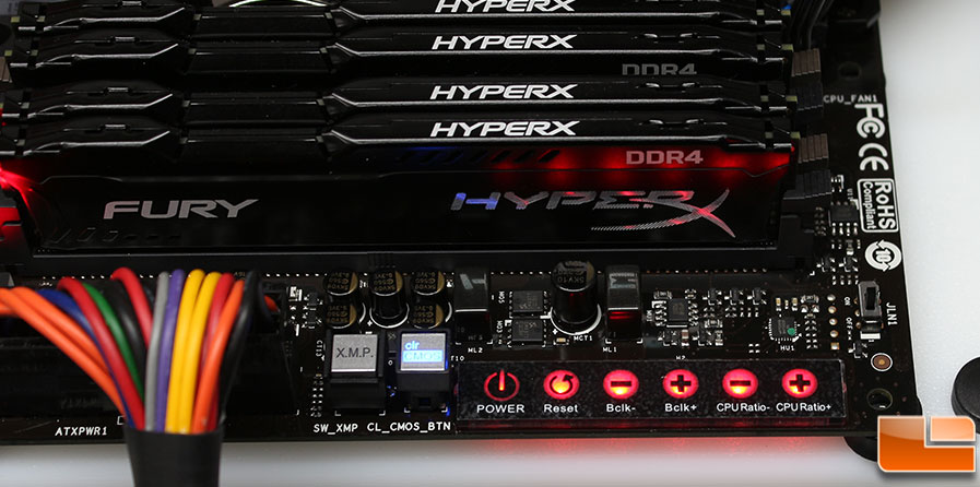
Next to the motherboard power connector, we have two physical buttons, one to enable XMP and a clear CMOS button; both of which are pretty common on motherboard. Now for one of the unique features of the Gaming Z170X, the Touch sensitive buttons. None of these buttons are unique to BIOSTAR, however being Touch sensitive is. Here you have the standard Power, and Reset buttons, if you are doing testing outside of a case. Next there are buttons to increase the BCLK and CPU Ratio for overclocking.
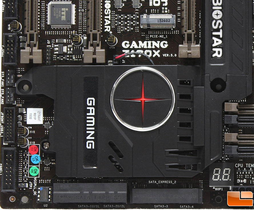
On the other corner we have the Intel Z170 chipset, which has a large heatsink on it, along with the BIOSTAR “armor” cover. Along the left edge of the motherboard there are various connections, which from the bottom is the front panel connections, the USB 3.0 internal header, two PWM fan headers, and a USB 2.0 connection. The front SATA connections have been split into two groupings, and are horizontal to the motherboard.
Those front mounted SATA ports include a total of three SATA express connections, which means there are a total of six SATA 6Gb/s connections. For each M.2 drive you connect, you will lose access to one row of connections in the left group. Following standard Z170 chipset protocol, the SATA ports are capble of RAID 0, 1, 5 and 10.
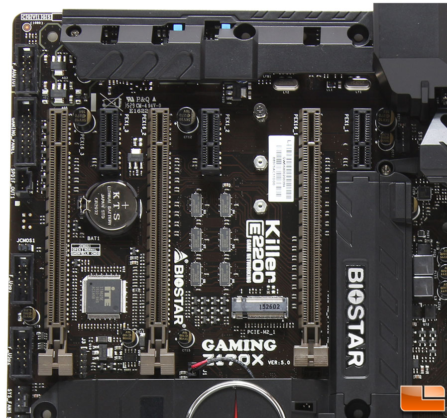
Moving along, we find the three PCI-E 3.0 x16 slots, which are configured for x16 or x8, x8 or x8, x4, x4 with support for AMD CrossFireX, but not NVIDIA SLI. Along with the three PCI-E x16 slots, there are also three PCI-E 3.0 x1 slots. Next to the first PCI-E X16 slot is one of the two M.2 32Gb/s slots. The other is hidden beneath a cover, which we will remove in a moment. Along the edge there are several connectors, the two USB 2.0 headers (one of which we saw previously), a BIOS clear jumper, SPDIF header, Gaming Commander header and the front audio connections. Right next to the PCI-E x1 lot on the far right, there is another PWM fan header that is partially hidden by the plastic heatsink cover.
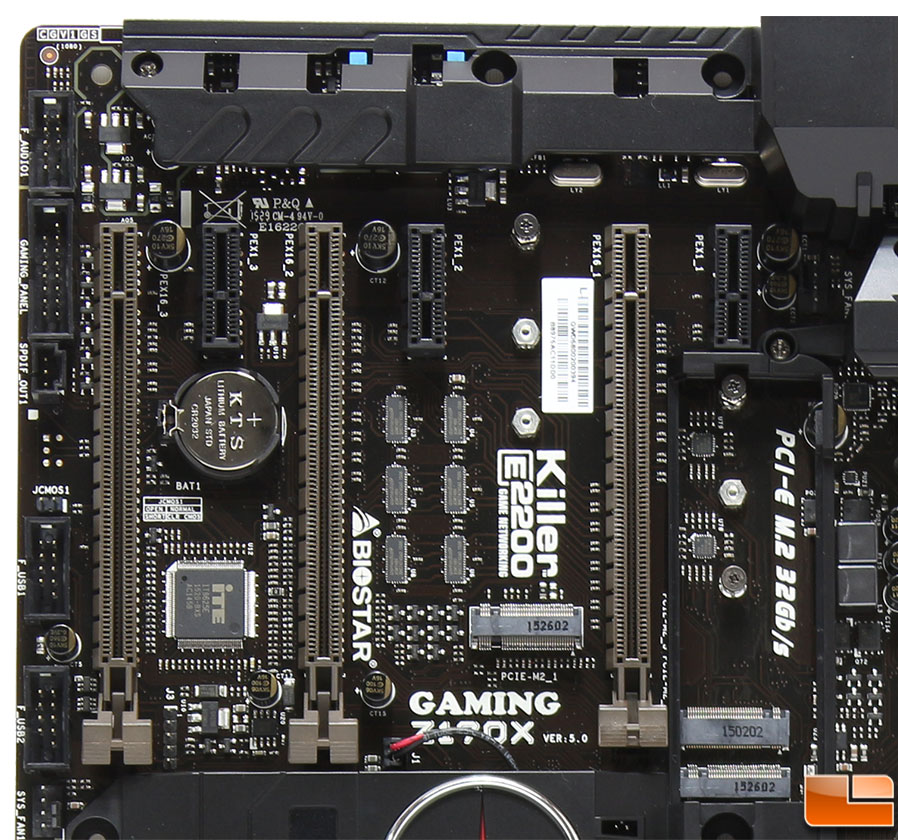
Nothing really different to see here, except that the cover on the hidden M.2 slot has been removed. It is held in place with a clip that can make it a little difficult to removed. Once it is removed, taking a look at the bottom of the cover, there are two tiny guides on one end of the cover and the main clip that will clip next to the M.2 slot. At first, I was a little confused thinking there are actually three M.2 slots, which there is. Two PCI-E M.2 Gen 3, and one PCI-E M.2 Key A. Two of them are for storage, while the Key A slot is designed to support WiGig and WiFi modules.
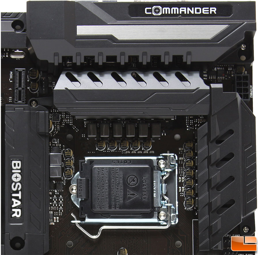
Moving to the last section of the motherboard it contains the Intel socket 1151, and while there isn’t much to see here, we can get a close-up view of the armor shielding covering the heatsinks; remember all this shielding is plastic, and for aesthetics only. If it’s not for you, it can be removed fairly easy. In the upper right corner, is the 8-pin motherboard AUX power connector.
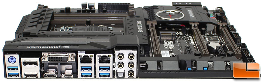
Finally, let’s take a quick look at the back I/O panel. Starting on the left we find an old school PS/2 port, and dual USB 3.0. Starting the video connections off is a DisplayPort, DVI-D, and 2 HDMI 2.0 ports. The new USB 3.1 Type-C connector is provided with the video connections. The next two clusters look identical but are slightly different. Both of them contain two USB 3.0 ports, and an ethernet jack. The difference is in the ethernet jacks, the first one (left) is controlled by the Intel I219V while the one on the right is controlled by the Atheros Killer E2201. Both of these can be combined for Dual GbE LAN. The final cluster is the audio cluster containing five 3.5mm audio jacks and the optical SPDIF out. These audio jacks are controlled by the on board Realtek ALC898.