GIGABYTE GA-A75-D3H FM1 Motherboard Review
GIGABYTE GA-A75-D3H FM1 Motherboard Layout
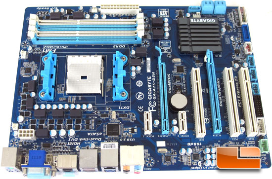
GIGABYTE has switched most of their motherboards over to a blacked out look. The GIGABYTE A75-D3H obviously isn’t one of them. Personally I’m not a fan of the blue and white color combination, but that wouldn’t stop me from buying a board if it has the performance and features I’m looking for. Overall I like the layout of the GIGABYTE A75-D3H, with the right case it would be plenty easy to hide all of the cables for cable management. There is plenty of breathing space for graphics cards if you plan on running AMD CrossFireX as there are two slots between the PCIe x16 slots.
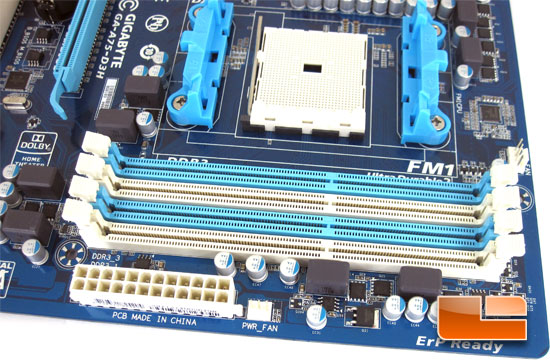
The GIGABYTE A75-D3H will support up to 64Gb of system DRAM in the four 1.5V DIMM sockets. There is also support for DDR3 up to 2400MHz (O.C.) in a dual channel architecture. To the back right of the DIMM slots we can see the 4pin CPU fan header, and to the right of the 24pin motherboard power is a 3pin power fan header.
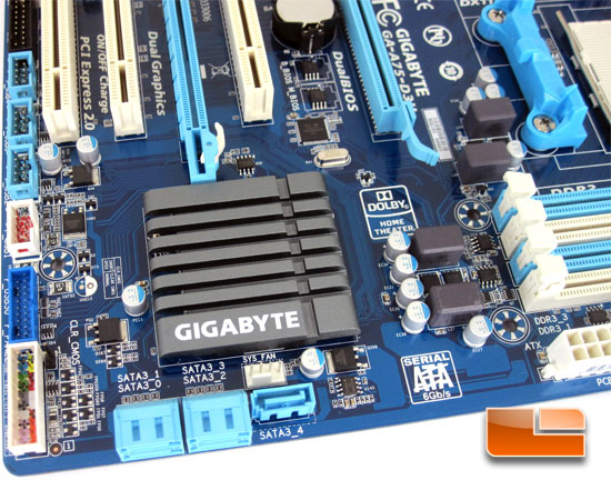
The GIGABYTE A75-D3H is fully capable of running six SATA III 6Gbps ports, here we can find five of them. Instead of employing a third party SATA III 6Gbps controller for the eSATA III on the I/O panel, GIGABYTE is using one of the AMD A75 SATA III ports. Just behind the SATA III port we find the first system fan header, this system fan header is a 4pin while the other system fan header is a 3pin that we will see shortly. Running our eyes up the left edge of the A75-D3H we can find the pin out for the front panel, the internal SuperSpeed USB 3.0 header, and four internal USB 2.0 headers. The white/red USB 2.0 header is the one you will want to use if you plan on taking advantage of the GIGABYTE On/Off charging technology. If you need to reset the CMOS the jumper for that is just to the right of the front panel header. GIGABYTE didn’t supply a jumper, so you will need to use something like a screwdriver to short the two pins.
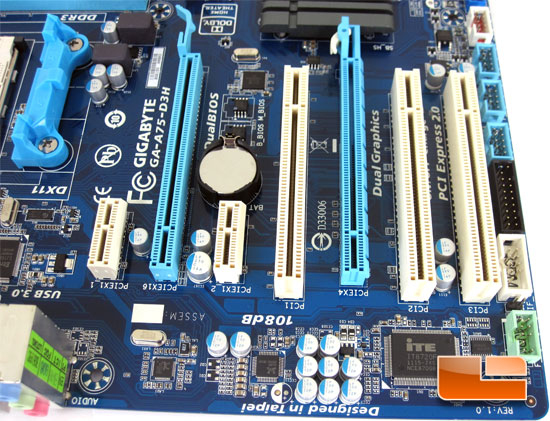
The GIGABYTE A75-D3H has a pair of PCIe x16 Gen 2 slots, a pair of PCIe x1 slots, and three PCI slots. The primary PCIe x16 slot runs at a full x16 bandwidt while the second PCIe x16 slots runs at x4 bandwidth. While there are two PCIe x16 slots, the AMD A75 chipset is only capable of supporting AMD CrossFireX technology. Picking up where we left off along the edge of the A75-D3H we can see the T.P.M. (Trusted Platform Module) header, COM port header, and the front panel audio header. Along the leading edge of the PCB we can find the ITE IT8720F Super I/O controller, the Realteck ALC889 High Definition audio controller, and the Realtek RTL8111E Gigabit Ethernet controller.
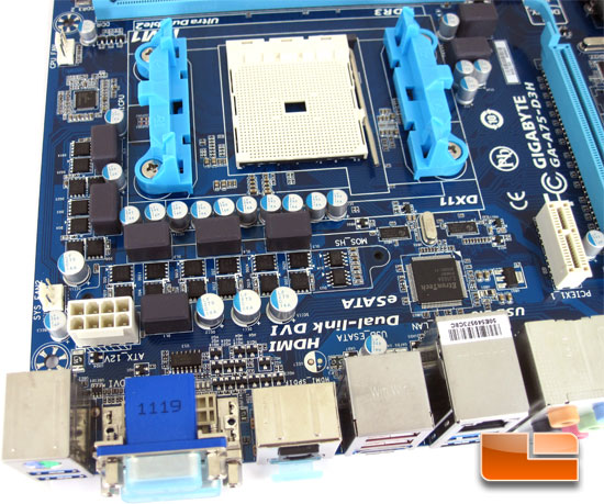
The area around the GIGABYTE A75-D3H is relatively bare. There isn’t any heatsinks on the PWM’s or any of the power delivery circuitry. While this makes CPU clearance a relative non issue, it may cause heat issues when overclocking. Just behind the Gigabit ethernet is the Etrontech EJ168A SuperSpeed USB 3.0 controller, and along the left edge of the A75-D3H we can find the 3pin system fan header labeled SYS_FAN2.
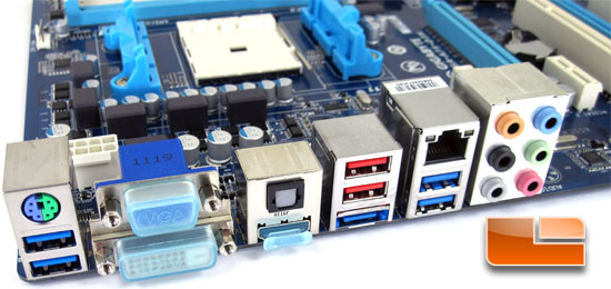
The I/O panel on the GIGABYTE A75-D3H is laid out a little quirky. On the left we have a single PS/2 port for either a mouse our keyboard, below that we have a pair of USB 3.0 ports driven by the Etron SuperSpeed USB 3.0 controller. I would have like to see the tradional USB 2.0 ports here so that we can keep our mouse and keyboard wires together if one of them is a PS/2. Other than that, everything is pretty typical of a AMD FM1 motherboard. We have a 15pin D-Sub VGA port, DVI, HDMI, optical SPDIF, a pair of USB 2.0 ports, four SuperSpeed USB 3.0 ports, Gigabit Ethernet RJ45 jack, and six 3.5mm audio jacks.

Comments are closed.