In-Win GRone Full Tower Chassis Review
Interior Thoughts of the GRone
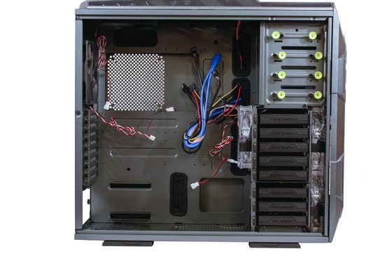
Time for me to look at the interior of the GRone chassis.
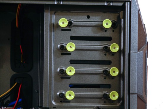
In-Win does things a bit different from what I have seen in the past on other chassis, instead of using screws, or various types of locking mechanisms; In-Win uses a push pin style of locks and we can move them from one set of holes to the next. To move the push pins from one mounting hole to the next all you need to do is pull on the push pins till it pops out, and then push it into the next corresponding mounting hole.
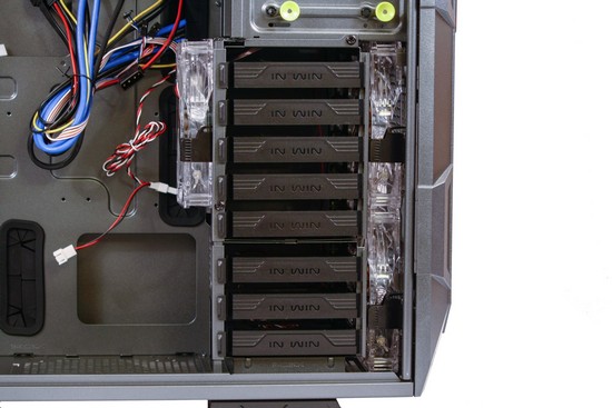
The GRone can handle up to eight 2.5/3.5 HDD/SSDs, In-Win also places two 140mm fans directly in front of the HDD cage, as well as another 140mm fan behind the HDD cage. The HDD cages can be removed from the chassis, there are 3 screws that secure these HDD cages to the chassis. 1 up to the right hand corner, one in the center left hand side, and one more screw is located on the bottom center.
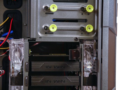
The HDD carriers removal is pretty straight forward.
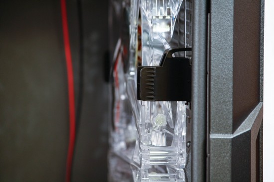
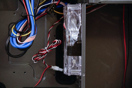
The front 140mm fans are not screwed into the chassis, all three front 140mm fans are held into by plastic clips.
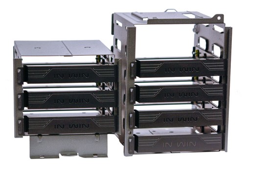
As I mentioned earlier that the HDD cages can be removed, and that there are two HDD cages. The upper HDD cage handles up to five 2.5/3.5 HDD/SSDs, while the lower HDD cage can handle up to three 2.5/3.5 HDD/SSDs.
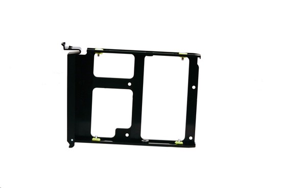
What the individual HDD carrier looks like. The 3.5 HDD mounting will not need the use of screws to secure it to the HDD carrier. While the 2.5 HDD/SSD mounting requires the use of the four inner mounting holes to secure these smaller drives to the carrier.
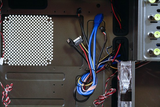
Looking at the front IO motherboard connectors, the Molex connector is used for the included fan controller, the exterior SATA connector gets a SATA power cable, and SATA DATA cable, and we get a standard USB 3 motherboard connector, a USB 2 motherboard connector, and the power/HDD LED connectors, and finally the on/off/reset motherboard connectors.
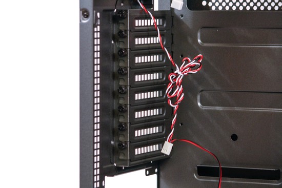
In-Win uses vented PCI port covers that we can reuse.
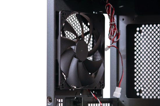
Looking at the 140mm rear exhaust fan.
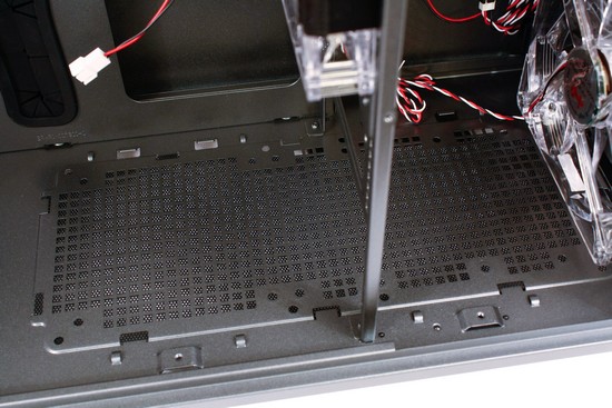
In order to install a lower dual 120mm radiator into the GRone chassis, we have to remove the lower HDD cage.
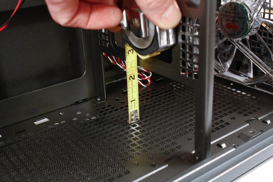
After doing a quick measurement I found out that we will be limited to using only a single row dual 140/120mm radiator with fans. I tested this out with my Danger Den dual 120mm, Dual pass, Dual row radiator I could fit the bare radiator in here but once the fans got installed I could not make it fit.
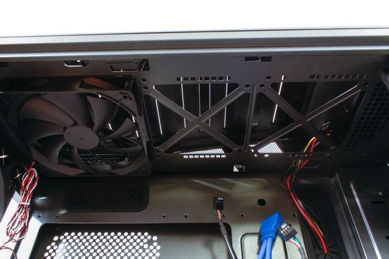
Up at the top of the GRone chassis we can fit another triple 120/140mm radiator up here. But up here we can use up to a dual pass, dual row, triple 120/140mm radiator.
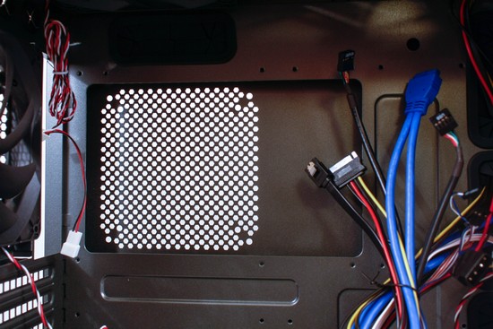
The CPU cutout does appear to be large enough to handle a multitude of different motherboards and their unique arrangements.
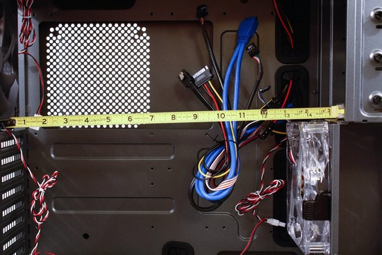
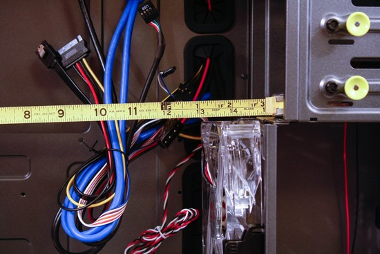
I left the rear HDD cage 140mm fan on for my measurement of the interior. We can use up to thirteen inch long video cards if the rear HDD cage fan is installed. But once it has been removed we gain an additional one and three quarters of an inch, that gives up fourteen and three quarters of total room.
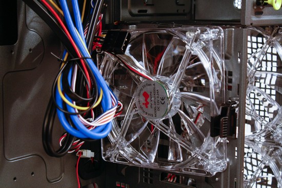
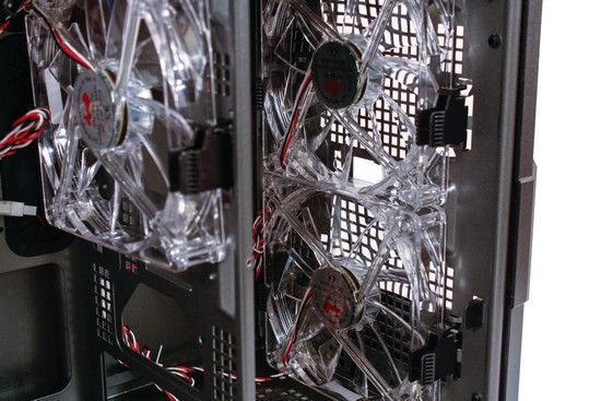
Looking at the included front three 140mm fans.
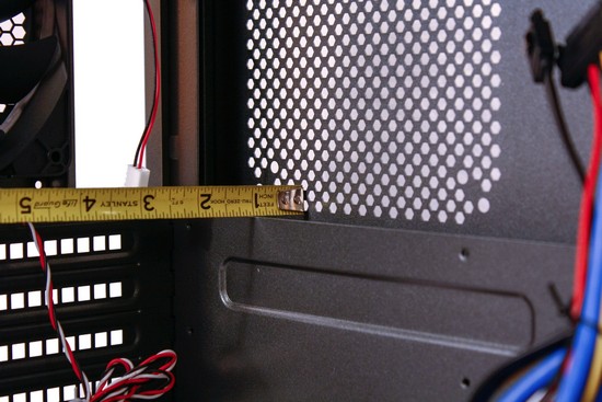
Doing a quick measurement behind the motherboard tray while the right hand side panel is installed, we get right at an inch of space here; which should be plenty of room to hide our PSU wires here, and or use a thin 15mm 120/140 fan on the right side panel.
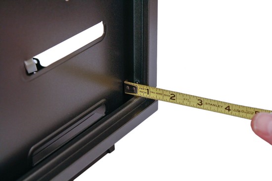
Doing a measurement behind the motherboard tray for a quick verification this reconfirms that we do have one inch of room behind the motherboard tray.
All of the edges of the GRone chassis were rounded off enough to keep my hands and or arms from getting cut up as I made my way around this chassis. Since I removed all of the side panels, and bezels off from the chassis prior to installing my computer hardware, I grabbed the front top right hand corner of the chassis, and then grabbed the bottom lower left hand corner of this chassis and twisted it just to see how much it would move. I am pleased to say that this chassis had very little movement; which tells me that this chassis is solidly built and that this chassis will not fail under the weight of our heavy, and expensive computer components.

Comments are closed.