Building Your Own Computer (DIY) Guide
Wiring The System
Now that all the hardware is installed in our system we can run the wires out to where they need to go. If you have never done wiring before don’t worry about this as it’s nothing more than a puzzle and you have all the right pieces. The motherboard will have the 24-pin ATX power supply connector (the biggest one) and the 4-pin 12V ATX power supply connector (the smallest one) installed. Also be sure to install the power supply fan header to the board during this step.
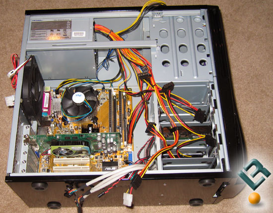
After a few minutes of wiring your system will look like the image below. And again, its not that hard as all the power connectors are ‘keyed’ so they can only be inserted to the proper location with the correct orientation. The hardest part of the wiring will be the system panel connector and it is best to go off this wiring diagram to figureit out quickly.
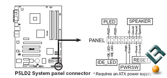
Since there is a positive and negative on the LED lights for the front power and hard drive lights the cables must be installed correctly. If you get it backwards the front power and activity lights will not work.
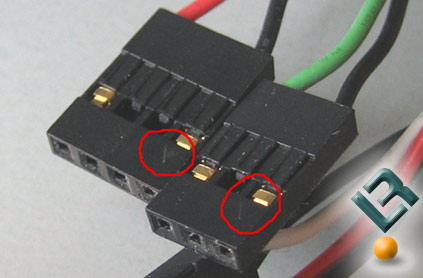
Each cable that goes to the system panel connector has an arrow on it that indicates Pin 1 location. The Pin 1 should be plugged into the lower numbered pin on the motherboard. You should be able to determine this from the manual and it is usally marked with a + sign. If you can’t figure it out take a random guess and it the front lights don’t work just flip the PLED and IDE_LED cables and it will work.

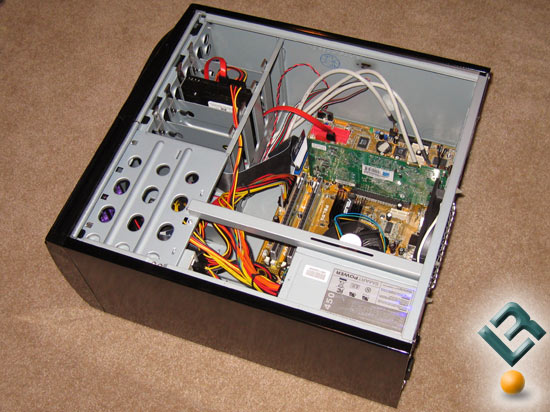
Nothing amazing with our wiring job and we didn’t use any zip ties here. You can go crazy with the wiring job and use zip ties and tape to make it all pretty, but this isn’t going to be a trailor queen computer and we didn’t care since there is no window on this case. Please note that the Western Digital power supply comes with two power connectors on it. ONLY USE ONE POWER CONNECTOR ON THE HARD DRIVE. Using both power connectors on the hard drive will cause it to burn up and void the warranty. The above image shows us using the SATA power connector on the Western Digital Hard Drive. Below is a picture of the wiring job from a different angle.
Now we can take a look at installing the cold air duct!
Comments are closed.