GIGABYTE G1.SNIPER2 Intel Z68 Motherboard Review
GIGABYTE G1 SNIPER2 Motherboard layout
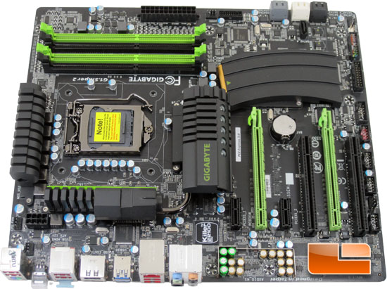
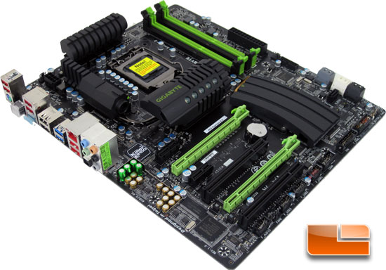
The GIGABYTE G1.SNIPER2 definitely stands out from the crowd. The GIGABYTE G1.SNIPER2 is built on an all black PCB with black and bright green expansion slots and DIMM slots. The heatsinks across the board are all built with the design of an AR-15 in mind.
Text
Text
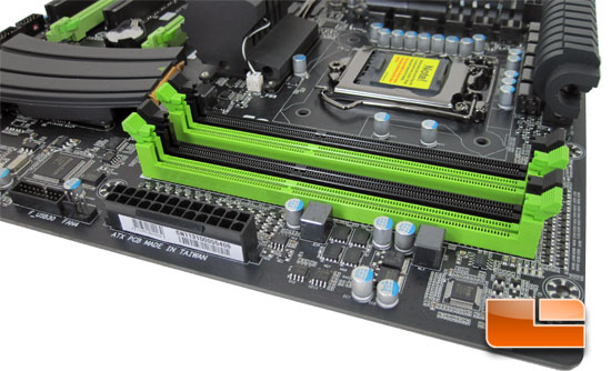
The GIGABYTE G1.SNIPER2 will support 4 DIMMS in a dual channel architecture. If you are planning on running the latest and fastest memory the G1.SNIPER2 will support 8GB DIMMS up to 2133MHz.
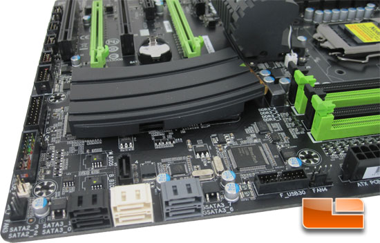
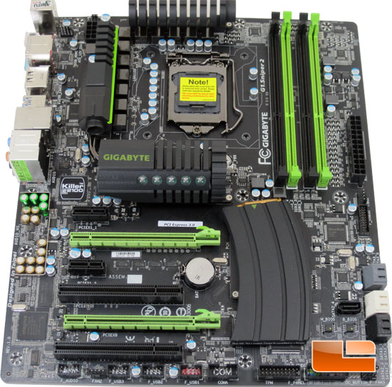
Spinning the GIGABYTE G1.SNIPER2 around we can see the first of five 4pin fan headers. Just to the left of the 4pin header is the front panel SuperSpeed USB 3.0 with the Etron EJ168 USB 3.0 controller right behind it. The GIGABYTE G1.SNIPER2 is epuipped with seven SATA Ports, the pair of grey SATA ports are SATA III 6Gbps controlled by the Marvell 88SE9172 IC right behind the ports, the white SATA ports are also SATA III 6Gbps though these are controlled by the Intel Z68 chipset. The remaining three black SATA ports are SATA II 3Gbps and are also controlled by the Intel Z68 chipset. Directly behind the pair of SATA II ports are the two separate BIOS chips. Beneath the mock AR-15 clip is where we can find the Intel Z68 chipset being kept nice and cool by the unique heatsink. Working our way up the edge of the SNIPER2 we can see the second 4pin fan header, followed by the front panel Quick Boost connector, front panel header, Trusted Platform Module (TPM), Serial Port header, and three front panel USB 2.0 headers.
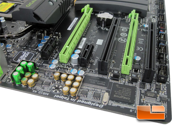
Picking up were we left up on the edge of the G1.SNIPER2 we have the third 4pin fan header, SPDIF out, and the front panel audio. The first of the chips along the leading edge of the GIGABYTE G1.SNIPER2 is the CREATIVE CA20K2 high definition audio codec, next to the Creative chip is a HYNIX H5DU1262GTR-E3C, this is a SDRAM DDR400 (3-3-3) 128MB memory module. Just if front of the first PCIe X16 slot is the series of solid caps and remaining circuitry for the Creative Audio. To the left of the PCIe X1 slot is the Bigfoot Networks Killer E2100 network card that has been integrated into the GIGABYTE G1.SNIPER2 motherboard. The GIGABYTE G1.SNIPER2 has a pair of PCIe x1 slots, a pair of PCIe X16 slots (1 x16x or 2 x 8x) and a pair of PCI slots. The layout of the PCIe x16 slots has enough spacing for sufficient cooling between a pair of graphics cards.
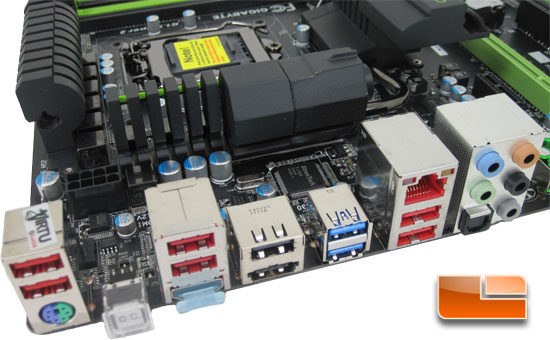
The GIGABYTE G1.SNIPER2 features the usual suspects at the I/O panel with the exception of the O.C. button. There is a grand total of nine USB ports, two of which are SuperSpeed USB3.0 (blue), a single keyboard/mouse combination PS/2 port, HDMI, RJ45 LAN port, five audio jacks, and an optical SPDIF out.

Comments are closed.