DFI LANPARTY UT ICFX3200-T2R/G Motherboard
Board Layout
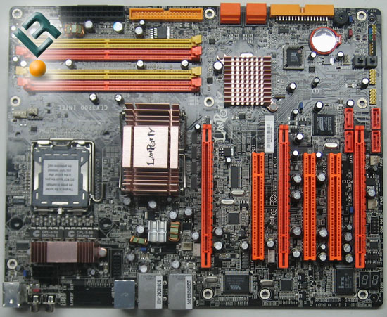
As you can easily see from a quick glance at the board, DFI cannot ever be accused of lacking color on their boards! This line from DFI has been characterized with the bright colors from the beginning of the line. It makes for a great reason to do some mods on your case to show off the color!
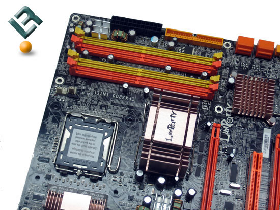
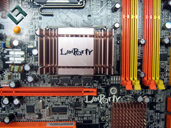
The top right of the board is where we find our DDR2 slots. This board supports up to 8GB of DDR2 memory in either single or dual channel configuration. To the right of the Dimm slots, we have the 24-pin power connector, and just under that we have the lone IDE connector. These are both positioned very well, off to the edge of the board which certainly helps keep wiring nice and clean.
To the left of the dimm slots, we have the large heat sink that sits on the RD600 north bridge. This seems to do an adequate job of cooling, but as always, we recommend taking off the stock TIM and adding a thermal product of your choice. Let’s take a closer look at the heat sink…
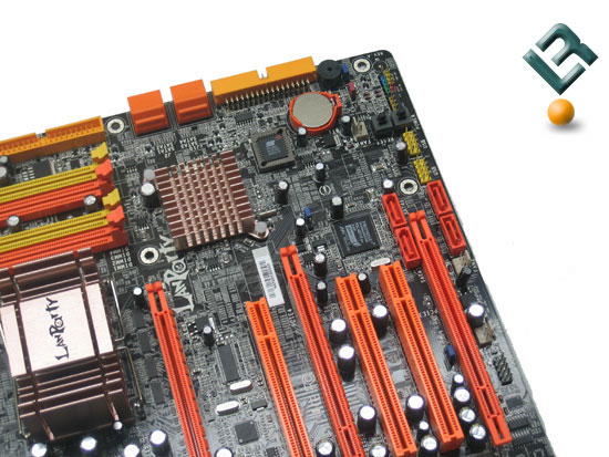
At the bottom right of the board, and just under the IDE connector, we have a series of four SATA ports. These are powered by the ATI SB600 south bridge, and support four SATA drives at speeds up to 3Gb/sec, as well as RAID 0, 1 and 0+1. Right under those SATA ports, we have the floppy connector. Once again, the SATA and floppy connectors are all on the edge of the board. DFI certainly thought through the layout of the board! To the left of the SATA ports, we have another heatsink. This one sits right on the south bridge and also seemed to do a good job of cooling. Under the heat sink is our BIOS chip, and right under the BIOS chip is the battery for the board.
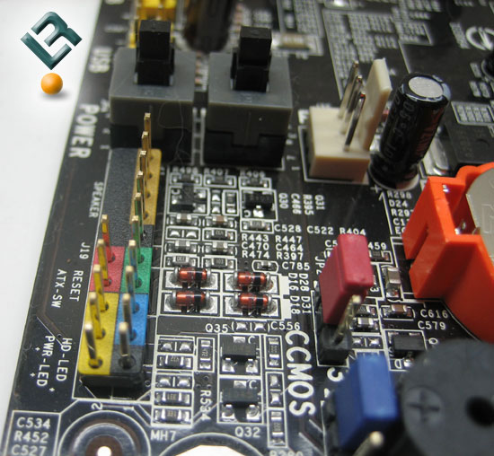
Taking a closer look at the bottom right corner of the board, we have our front panel connection pins. We also have our clear cmos jumper here. At the very top of the pic, we have one of my favorite features on a board… on-board power and reset buttons! These are a god-send for reviewers and enthusiasts alike.
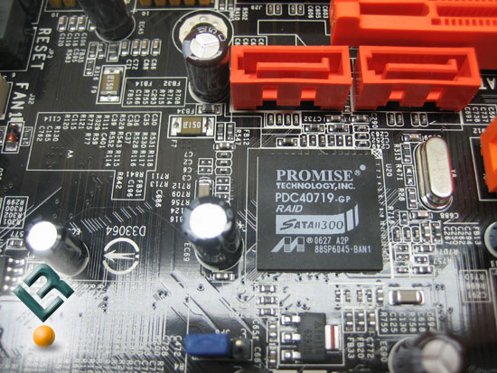
Also located at the bottom of the board we find four more SATA ports. These are powered by the Promise PDC40719 controller, and supports SATA2 with speeds up to 3Gb/sec and RAID 0, 1, 0+1 and RAID 5. There is certainly a potential to have a lot of HDD space with this board!
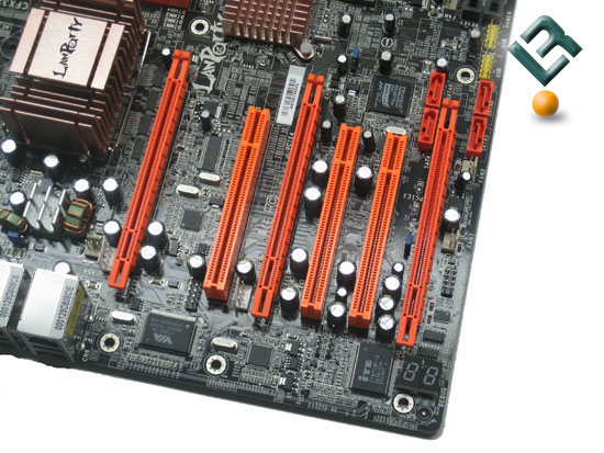
At the bottom of the board, you can see that we have our PCI and PCI/E connectors. The board sports three legacy PCI slots and has a total of three x16 PCI/E slots. In their specs, DFI clearly states that the three slots are for housing two ATi graphics cards in a Crossfire setup, as well as allowing space on the third x16 slot for a physics card. Note: the board is able to run two ATi cards in Crossfire at x8 bandwidth speeds.
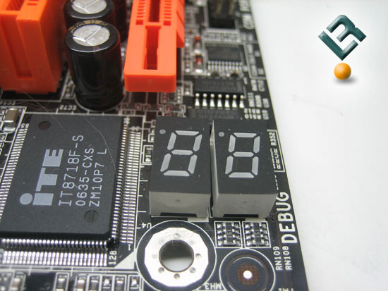
Also on this part of the board, we see an LED readout for troubleshooting the board. This actually came in handy during the course of this review. Take a closer look at the LEDSs.
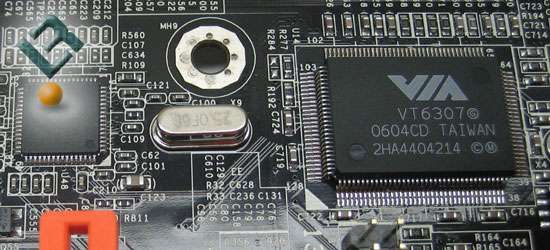
Also on the bottom left of the board, we have our LAN chip…
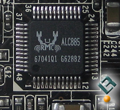
The audio solution is provided by the Realtek ALC885, which provides 8-channel, high def audio. DFI does things just a little different with their audio. We can get a better picture of this by looking at the top left of the board.
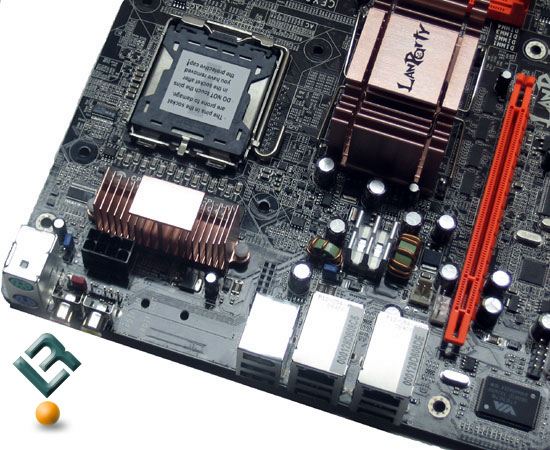
As you can see , the top left provides us with the CPU socket, an 8-pin power connector, and another heat sink for the cooling of the power on the board. As I mentioned, this is where you can see something a little unique on the LanParty boards. Notice the big gap under the PS/2 connections. That is where many times we would find our audio connections, but they are not there. And this is why…
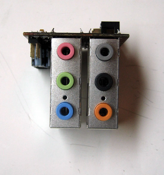
DFI makes their audio in an add-on riser card. This is certainly unique, but it does make for one extra step in setup if you need to use the on-board audio.
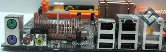
Just a quick look at the back I/O inputs for the board shows us the big gap left without the riser card being installed. You also have your typical PS/2 ports, six USB, one firewire an two LAN ports.
Alright, let’s move on!
Comments are closed.