ABIT’s AA8-DuraMAX — The Next Winner or Loser?
The Layout:
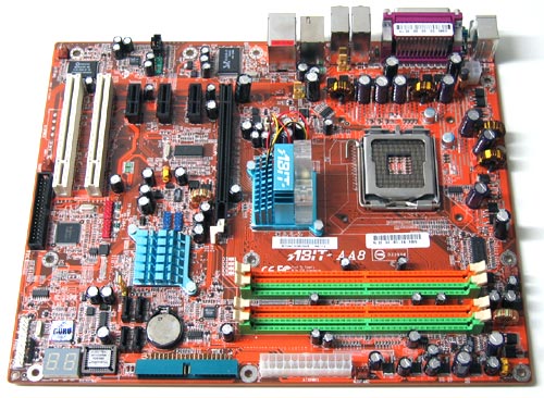
The ABIT AA8-DuraMAX has a layout similar to that of ABIT’s previous generation boards. All of the connectors for the board were positioned on the edge of the board which helps to keeps cables out of the way, and helps in the efficiency of cooling the board. Our only gripe with the way ABIT positions their connectors is the floppy drive connector located right smack dab at the bottom of the board. I know many users have eliminated having a floppy drive in their system, but for the few of us that still run one will find running “clean” cables to be fun for this floppy header. Other than that one minor gripe the overall layout of the AA8-DuraMAX looks solid and well thought out.
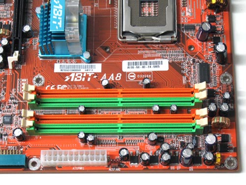
Here we can see the 4 DIMM slots that officially support Dual-Channel mode up to DDR533, with a maximum of 4GB installed memory.
These DIMM slots only support 240-pin DDR2 memory, this means that none of the original 184-pin DDR1 memory will be able to work on this board. ABIT was nice enough to color code the DIMM slots so even the first time DIY (Do-It-Yourself) builder can easily build a system with this board. On the ABIT AA8, it is recommended to use 2 identical sticks of memory in either slots DIMM1/DIMM3 or DIMM2/DIMM4. If you want to run with all four DIMM slots full, you can! Just be sure to keep your DDR2 memory modules paired together in slots DIMM1/DIMM3 AND DIMM2/DIMM4.
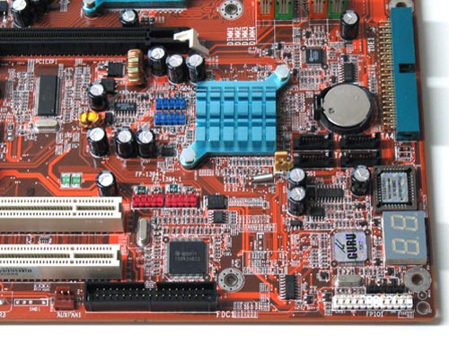
Here we see the bottom corner of the board. Unlike the previous Intel south bridge (ICH5R) the ICH6R south bridge chipset is passively cooled by an aluminum heat sink. Just to the right of this we have the CMOS battery. Just below the battery we can see that ABIT has placed not two, but four SATA connectors here that use the ICH6R south bridge.
With the use of SATA drives users will be able to get data transfer rates to up to 150 MB/sec!
ABIT does include four SATA connectors, so if you wanted to run four hard drives you have the cables to do so. Just below the SATA headers we find the BIOS and uGuru chips and LED diagnostics display. The single IDE and floppy connectors can also be seen on both the right and lower edges of the AA8-DuraMAX. On the right side of the south bridge we can find the headers for the IEEE 1394 (red) and USB 2.0 (blue) connections.
Last, but not least the CMOS clear jumper tab (yellow thumb tab) can be found on the lower right hand corner of the south bridge heat sink.
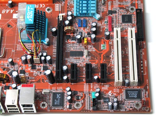
Here we see the PCI Express x16 graphics slots, three PCI Express x1 I/O slots, and two PCI slots. Located along the bottom edge are the CD audio and front-panel audio connectors as well as the Realtek audio an LAN chips. If you note there is a spot on the board to the right of the last PCI slot for a third power connector (labeled ATXPWR3) that isn’t installed. We were curious to see why this was here, so we asked ABIT about the spot and if future revisions of the board would have an additional power header located here.
“The original purpose of the ATXPWR3 connection is to provide more stabilized 12V for the board. The PCI-E device of the main power is depending on the 12V. According to Intel specification of the +12V current limit, each pin on the ATX main power connector can support ~6A. The low limit of the 12V has to be up to approximately 11.4V (-5%) or above. (The PCI-SIG features both “PCI-E x1” and “PCI-E x16” interface, former PCI-E x 1 requires 0.5 A and the PCI-E x 16 requires 5.5 A.) We have found that the hardware design of AA8 is able to deliver stabilized 12v for any current PCI-E devices. In summary, the load on 12V is adequate without the need of extra ATXPWR3.“
So we can conclude that during development ABIT was unsure what the final power requirements of the PCI-E interfaces would be. Once it was determined that enough power was present they took the feature off and didn’t re-design the board. I’m not sure if the tracings go through to the PCI-E slots on the final revision boards, but if they do I’m sure those interested in voltage mods might look here as a point of interest.
It is also here that we see the Realtek A880 codec chip to provide digital-to-analog and analog-to-digital conversions. This chip provides high quality sound and can do so for eight channels of 24-bit, 96KHz/192KHz (input/output). The AA8-DuraMAX features a Realtek chip, the RTL8110S, for Gigabit Ethernet networking and the Texas Instruments chip for the fire wire. Sadly both the fire wire and ethernet use the 32-bit, 33MHz PCI bus connection and not the faster PCI Express bus connection. Hopefully future boards from ABIT will include chips that utilize the latest advances in technology.
Sound/LAN/IEEE 1394/IO Ports
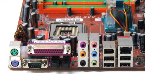
Despite the many changes in technology on the board the Back Panel I/O remains pretty much the same. Here we find the Keyboard and Mouse PS/2 ports, 4 USB2.0 ports, 1 Parallel port, 1 Serial port (COM1), 1 RJ45 LAN port, 1 IEEE 1394 port, S/PDIF In and Out ports, and
six different analog audio ports four stereo ports for eight-channel audio, plus two inputs.
Well, that about does it for the layout and board features; let’s take a look at the BIOS!
Comments are closed.