The Gigabyte P35-DS3R Motherboard Review
Board Layout
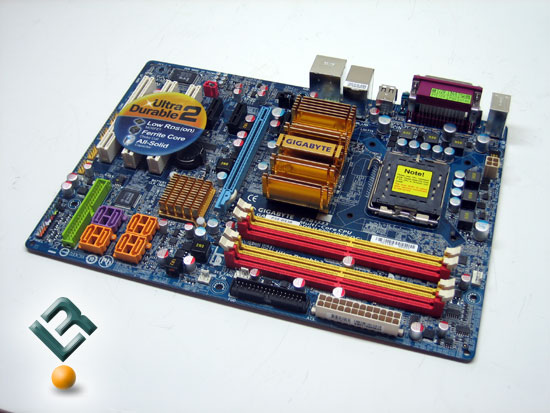
With a quick glance at the board, you can see the Gigabyte decied to remain with the blue-green color of the PCB that they have come to be known for. I know that is all subjective, but I kind of like this color, and it does make Gigabyte boards easy to spot! A quick glance at the board also makes it easy to see that it is just a tad smaller than a lot of other boards. Gigabyte packed a lot into this board though. Let’s get an up-close view!
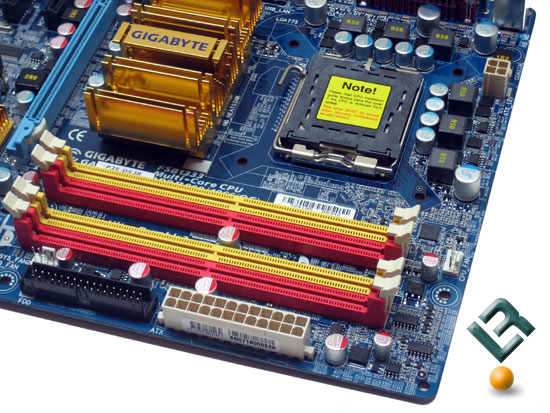
The top left of the board is where we find our CPU socket, which is clear of any obstruction, so you should have no issues using nearly any water or air cooler. You also can see here the massive heatsink that they have on the Northbridge. We also have our dimm slots here. The P35 chipset supports DDR2 memory at speeds of 1066/800/667/and 533 in dual channel architecture up to 8GB total. Notice the inclusion of 1066 memory here. While there are no official JDEC standards for 1066 yet, this board is ready for it!
We also have our 24-pin power connector and floppy connector located at the far right edge, which is an optimal placement for cable management.
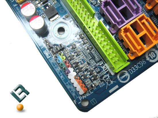
The bottom right of the board is where we find our eight SATA connectors, which are all SATA2 compliant. Next to the SATA connetors, we have our southbridge, which comes in the form of Intel’s newest ICH9R chipset. This chipset has an aluminum heatsink on it, and it did become quite warm as we ran the board under normal circumstances. Just under the SATA connectors, we have our lone IDE connector. Under the IDE connector, we have our front panal connector pins, which are colored to help the user with ease of setup. Here is just a little closer look at the pins.
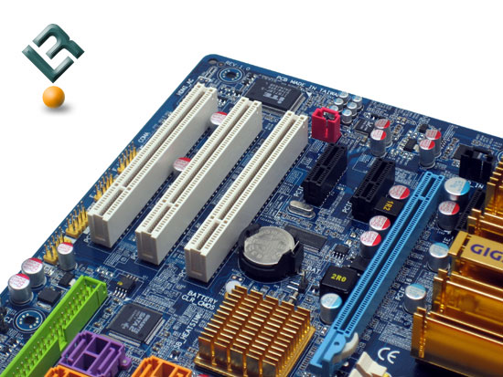
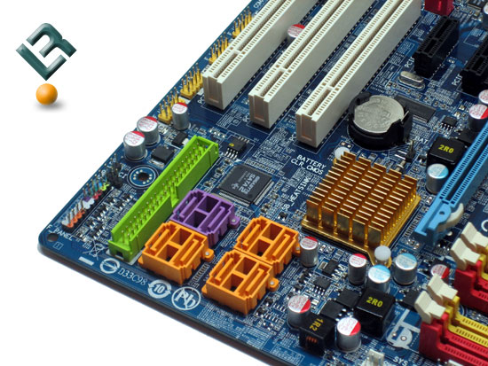
The bottom left of the board is where we find our pci and pci-e slots. The P35-DS3R has a total of three legacy pci slots, three x1 pci-e slots and one x16 pci-s slot for your graphics card. The three x1 slots are probably overkill for any board at this time, but they are there none-the-less.
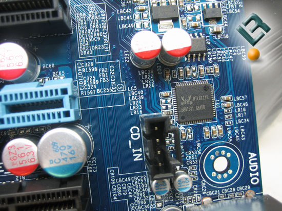
This area of the board is also where we find our audio solution for the board. This board has the Realtek ALC889A Audio controller, which supports 8-channel High def sound.
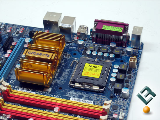
The top left of the board houses the location of the four-pin power connector, and givesus another opportunity to see the massive heatsink on the northbridge of the board. Gigabyte also toots their own horn in their use of special capacitors. This clip from their web site will explain it…
Ultra Durable 2 -Designed with Top Quality Highly Efficient ComponentsUltra Cooling – Low RDS(on) MOSFET Design
Low RDS(on) MOSFETs specially designed to produce lower switching resistance for faster electric current charging and discharging.
Low Power Loss – Ferrite Core Choke Design
Ferrite core chokes comprised of a compound of iron oxide and other metal elements whose properties hold energy much longer than common iron core at high frequency.
Longer Life – All-Solid Capacitor Design
Solid capacitors contain a solid organic polymer, while electrolytic capacitors use a common liquid electrolyte, hence, the terms solid capacitor versus electrolytic capacitors.
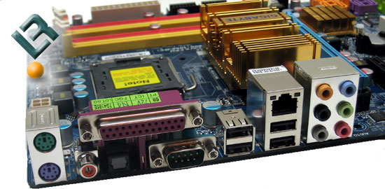
On the back I/O panal, we see our PS/2 mouse and keyboard connectors, as well as legacy parallel and serial ports. We also have a total of four USB connections, a gigabit lan port, and all of our audio jacks, including both Coax and Optical SPDIF connections. Let’s move on!
Comments are closed.