Gigabyte GA-965P-DQ6 Motherboard Review
Board Layout
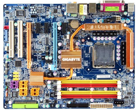
As you can tell from the first glance, Gigabyte has continued the tradition of keeping lots of color on their boards. With blue pcb and the colorful plastics, there is hardly a board that can say it has as much color as Gigabyte boards.
Another thing that sticks out at you when you first look at this board is the heatpipe. The seemed to do a fine job of keeping our board cool, but there is more to it than meets the eye… take a look at the back of the board:
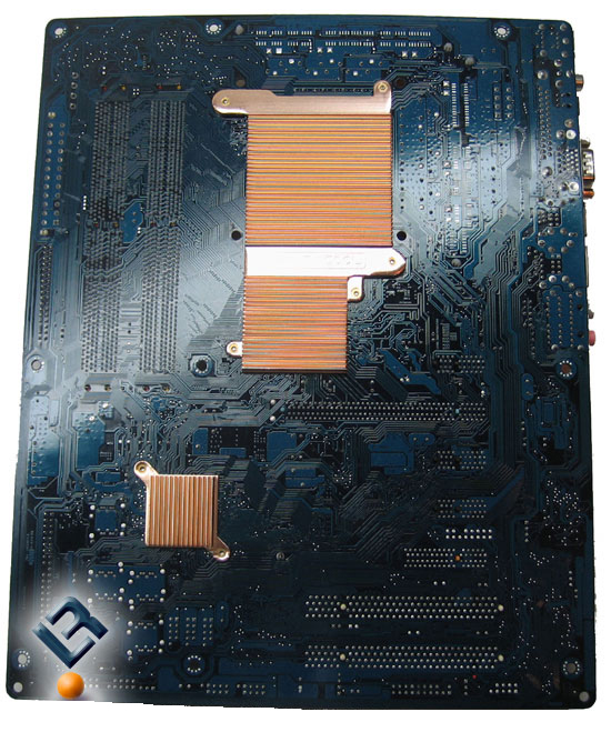
The heatpipes are aided in cooing by copper plates on the bottom of the board. The placement of these plates are there to help disapate heat. There was only one problem that we could forsee with this setup… How will you use some of the coolers that in the market and that need the retention bracket that many of them use to hold the cooler in place?
The answer was not real difficult: use longer screws. That is an easy fix, but that last thing I would want is to be putting together a new system some night and find out (after retail stores have closed) that I need longer screws, but will have to wait until the next day to get them. I guess most places have a 24-hour Wal-Mart these days, but this can still be annoying and troublesome.
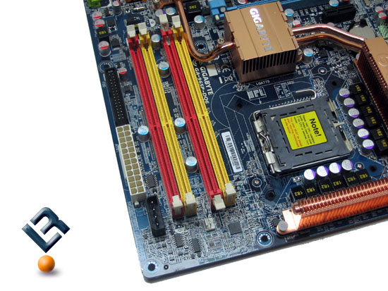
The top right of the board is where we find our dimm slots. This board supports DDR2 ram in a single and dual-channel configuration. It supports up to 8GB of ram, and is able to run at the stadard speeds of 400/533/667/and 800.
We also see a 4-pin molex power connector here on the board that is used to provide just a little extra juice for high powered graphics cards. Just under the 12v power is the 24-pin power connector for the board, and then we see under that the floppy connector for the board. All of these connectors are located at the edge of the board which makes it very nice for cable management.
One thing to note here is that the placement of the top pcie slot makes it difficult to move the dimm slots clips to install or remove your ddr modules. It is not impossible to do, but it is very, very tight.
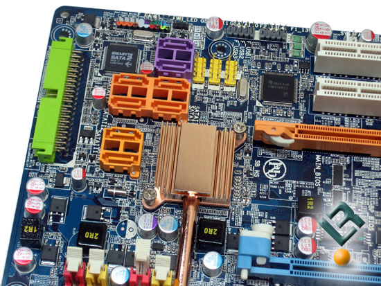
The bottom right of the board is where we find our lone IDE connector. Once again, the placement is on the edge of the board. To the left of the IDE connector we find our SATA connectors. These are color-coded to let you know that they are controlled by different controllers on the board. The six orange colored connectors are powered by the Intel
ICH8R southbridge and supports RAID 0, 1 5 and
10, while the two purple and the IDE connector are powered by the Gigabyte controller and support RAID 0, 1 and JBOD.
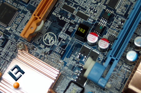
Right next to the top orange SATA connectors, we find the Intel southbridge, which is covered by a coper heatsink for cooling. Underneath the purple SATA controller is where we find our color coded front panel connectors. We kind of take it for granted now, but it sure is nice having them color coded!
To the left of that, we see many USB and Firewire headers that will help you to manage a great number of devices for your system.
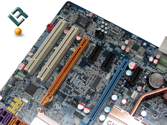
The bottom left of the board is where we find our pcie and pci slots. This board sports two legacy pci slots at the very bottom of the board. It also has three x1 pci-e slots and two x16 pci-e slots. The two x16 slots are able to run two ATi cards in a Crossfire setup (2x x8 speeds). Also on this part of the board we find our audio chip.
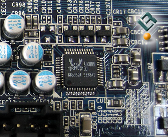
Audio is powered by the Realtek ALC888DD Audio Codec, and provides 8 channel high definition sound.
One thing that had me scratching my head was the use of two different types of pci-e release tabs. I am not sure why Gigabyte did this, and it really does not affect anything, but it still looks kind of funny.
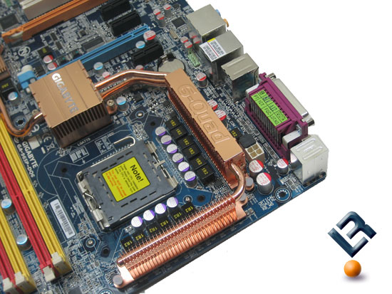
At the top right of the board we get a great view of the copper heat-pipe system that is used on this board. It does get warm while the board is in use, so it must be doing something. We did not have any type pf heat related problems while using this board.
You can also see the CPU socket in this shot. There is nothing that would hinder the installation of any type of cooling you would want to use.
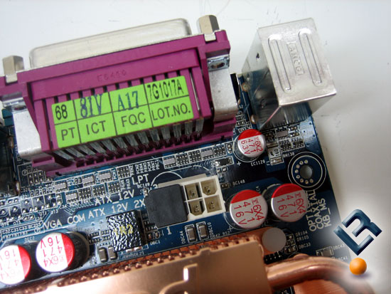
This Gigabyte board has an 8-pin 12v power connector located right next to the back I/O panel. It is located pretty well here at the top of the board, and allows you to keep wiring out of the way.
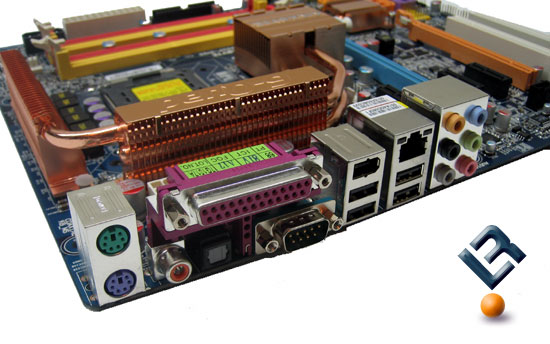
Looking at the back I/O panel, you can see that it has the two legacy PS/2 ports as well as legacy parallel and serial ports. We also have four USB ports, our lan and firewire ports as well as our audio jacks and one optical and one coaxial SPDIF out port.
Comments are closed.