Core Temperatures Examined
Introduction:
After posting our recent Prescott Overclocking article the sharp eyes of many review sites, online retailers, and enthusiasts noted some large temperature differences between our articles. If you have not been following our Prescott coverage let me give you a quick run down. The initial Prescott review was written by me (Nathan Kirsch) using the ABIT IC7-MAX 3 and the overclocking article was written by Jason Petermann on his ASUS P4C800-E Deluxe board. There was a large difference in temperatures noted between the two boards and due to the feedback from this I’ve spent the past couple weeks running our 3.2E Prescott on both boards. After using identical settings for testing we found that the results are not only surprising, but they also point out an issue that needs to be better understood by enthusiasts!
How “Core” temps are found:
Since this whole situation started with our Prescott the it will be the processor used for this example. Many people think that core temperatures found using Mother Board Monitor or other utilities is done by a thermal probe on the motherboard. This is possible, but with the boards in question today that is not the case. There is no temperature sensor found on the board in the socket area of the ABIT IC7-MAX3 and the ASUS P4C800-E Deluxe! The reading actually comes from a thermal diode found in the Prescott die.
We found that the Intel has incorporated two methods of monitoring die temperature in the Prescott; the Thermal Monitor (also known as: “Prochot/Thermtrip sensor”) and the thermal diode. To better explain what these do it’s best to quote directly from Intel:
What measures the temperatures:
“There are two independent thermal sensing devices in the Pentium 4 processor on 90 nm process. One is the on-die thermal diode and the other is in the temperature sensor used for the Thermal Monitor and for THERMTRIP#. The Thermal Monitor?s temperature sensor and the on-die thermal diode are independent and physically isolated devices with no defined correlation to one another. Circuit constraints and performance requirements prevent the Thermal Monitor?s temperature sensor and the on-die thermal diode from being located at the same place on the silicon. The temperature distribution across the die may result in significant temperature differences between the on-die thermal diode and the Thermal Monitor?s temperature sensor. This temperature variability across the die is highly dependent on the application being run. As a result, it is not possible to predict the activation of the thermal control circuit by monitoring the on-die thermal diode.”
From the above statement it’s clear that the Thermal Monitor is used to control the processor temperature by activating the TCC (Throttling) when the processor silicon has exceeded its maximum operating temperature. The TCC reduces processor power consumption as needed by modulating (starting and stopping) the internal processor core clocks. Other than the Thermal Monitor Intel placed a thermal diode on-die to give end users a way to monitor temperatures of the core.
How the temperature is figured:
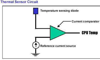
“The processor temperature is determined through an analog thermal sensor circuit comprised of a temperature sensing diode, a factory calibrated reference current source, and a current comparator (see above image). A voltage applied across the diode induces a current flow that varies with temperature. By comparing this current with the reference current, the processor temperature can be determined.”
The temperatures we see using MBM5, ASUS Probe, and other monitoring programs come from the on-die thermal diode. Thanks to a thermal sensor (ie: Super I/O chip) located on the motherboard the data from the thermal diode can be used to monitor the die temperature of the processor for thermal management. This thermal diode is separate from the Thermal Monitor?s thermal sensor and cannot be used to predict the behavior of the Thermal Monitor.
What influences the reading:
Every processor has different amounts of leakages and is therefore unique. Since each processor is unique the readings between two processors should never be the same. One of the parameters used in the equation to determine the CPU temperature is the Diode Ideality Factor (A.K.A. the Non-Ideality Factor) which describes the behavior of the diode relative to a theoretically perfect diode. The ideality factor depends on the characteristics of each individual processor and will vary slightly from one chip to the next. According to the data sheet the range of ideality for the Prescott ranges from 1.008 to 1.0137. The temperature calculation should take this range in to account in order to improve the accuracy of the reading.
One other variable that influences the temperature accuracy is the “‘Series Resistance”, which is a measure of the resistance in the traces leading up to and away from the thermal diode. The Prescott data sheet shows that this ranges between 3.242 and 3.594 ohms. Some diode sensors have the ability to adjust for the temperature error caused by the resistance, some do not. Lastly, cross-talk from high speed signals to the thermal diode traces might also introduce an error.
Now that you have the basic understanding where the “core” temperatures are coming from lets get testing!
Comments are closed.