XFX 680i LT and 650i Ultra Motherboard Reviews
650i Ultra Board Layout
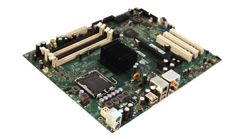
As you can see from the first glance, this board is a Nvidia reference layout, so what you are seeing will likely be a very common layout, if not the only one you see on this board.
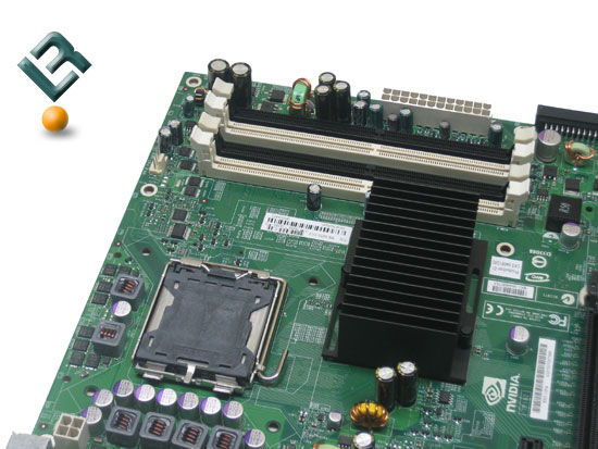
The top left of the board is where we see our Dimm slots. This board supports up to 8GB of DDR2 memory in Dual-channel configuration at speeds of 533/667/and 800 ddr. As we noted, this board does not support SLi memory mode, that is one of the features that was removed. Just to the right of the dimm slots we have our 24-pin power connector, located in a great spot at the edge of the board. To the left of the dimm slots, we see the beefy heatsink on the Northbridge. This sucker did get extremely hot during testing and overclocking. Some new thermal paste and fan would certainly help out in the overclocking of this board.
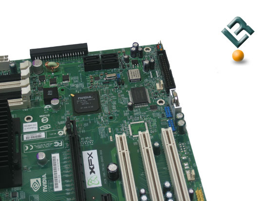
The bottom right of this board is where we find our lone IDE connector, placed correctly at the edge of the board. Just to the left of the IDE connector is where we find our SATA connectors. These connectors are powered by the Nvidia chipset, and are SATA2 compliant. They also support RAID in flavors of RAID 0, 1 and 0+1. Just to the left and under the SATA ports, we have out Clear CMOS and Bios chip. Under those, we have our floppy connector, and in the very bottom corner, we see our front panel I/O connections.
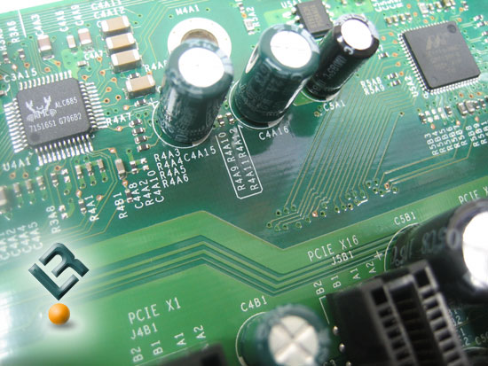
Right in the middle of this part of the board is where we find the southbridge, take a closer look…
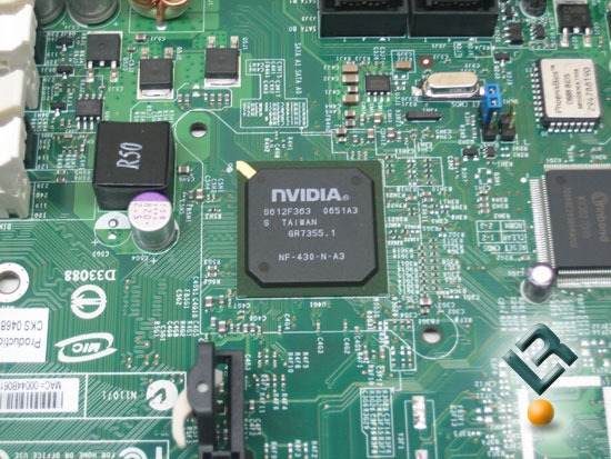
Notice there is not fan ontis chipset, and this baby needs one! If you are going to invest in this board and overclock it, you need to also get some type of a fan that you can cool this chip with.
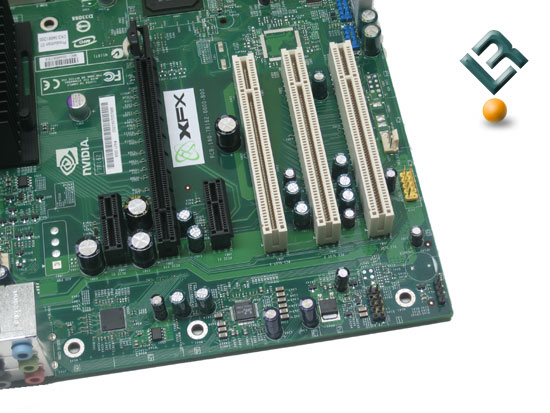
The bottom left of the board is where we find out pci and pci-e slots. This board only sports one pci-e, a cost cutting measure which means this board will not run in SLi. if want that ability, you will need to look at one of the other boards in this family. There are two x1 pci-e slots, as well as 3 legacy pci slots. We also find our lan and audio here in this area.
The audio on this board is powered by the Realtek ALC885, and provides 7.1 HD audio. The lan is powered by a Gigabit enabled Marvell chipset.
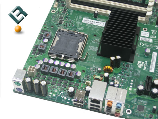
The top left of the board is pretty barren. It houses the CPU socket in the middle of this area. it also is home to our 8-pin 12v connector, which is located at the top left of the board. This is a prime position for this connector!
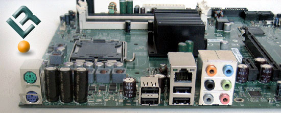
The back I/O port area also looks very barren. We have our PS/2 ports, our four USB ports as well as our LAN and audio jacks. That is all! Let’s look at the bundle and bios!
Comments are closed.