The AsRock ConRoe1333-eSATA2 & ConRoe1333-D667 Motherboard Reviews
The AsRock ConRoe1333-eSATA2 Board Layout
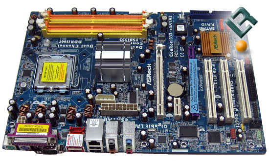
This is the first board that we have looked at in a while from ASRock that was not an mATX sized board, though it is not huge by any stretch. The layout is pretty simple, let’s look a bit closer…
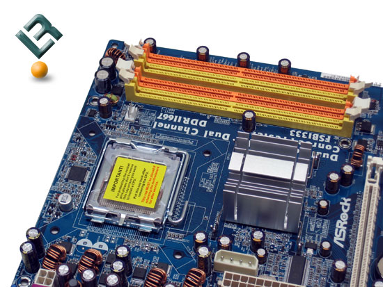
At the top right of the board, we find our dimm slots. The ConRoe1333-eSATA2 supports up to 4GB of DDR2 at speeds of 533 and 667 in dual channel configuration. You also see the aluminum heatsink that covers the northbridge. Heat was not an issue at all while using this board, so it must have been doing its job.
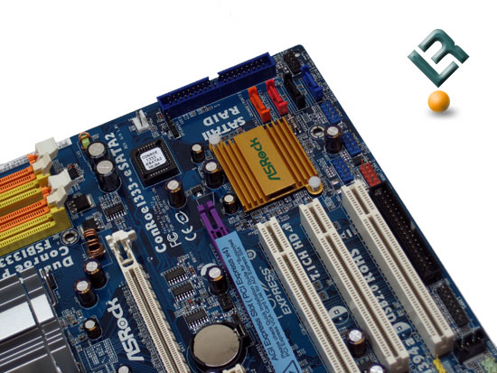
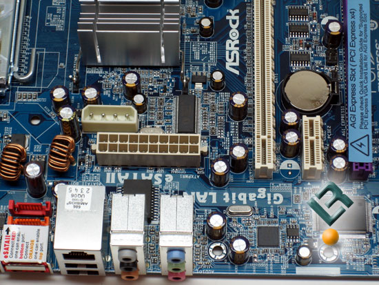
The bottom right of the board is where we will find our BIOS chip, IDE connector, as well as our four onboard SATA connectors. This board has four SATAII connectors, which supports 3.0 Gb/s, RAID (RAID 0, RAID 1, RAID 10, RAID 5 and Intel Matrix Storage), NCQ, AHCI and “Hot Plug” functions. You can see that ASRock also has placed a heatsink on the southbridge. As we said, we had no heat issues as we worked with this board.
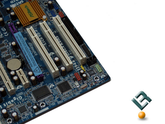
The bottom left of the board is where our pci and pci/e slots are located. The ASRock ConRoe1333-eSATA2 has three legacy PCI slots, one x1 pci/e slot and two x16 pci/e slots, which can be used to run a Crossfire setup with two proper ATi video cards.
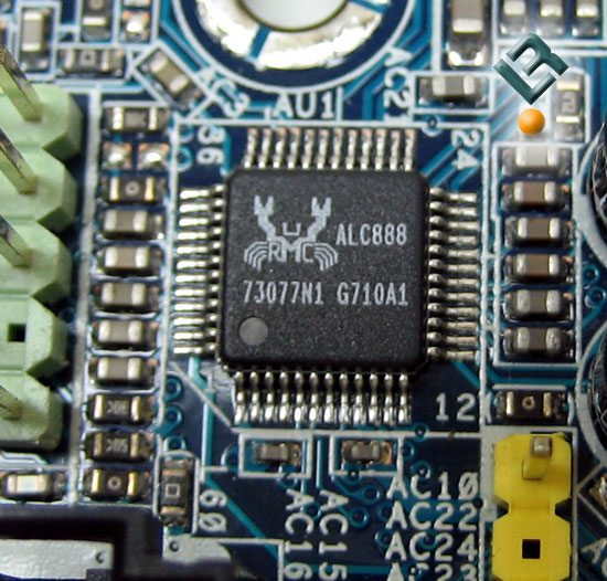
We also have our audio on this part of the board. Audio is powered by the ALC888 Audio Codec, and provides 7.1 channel HiDef sound.
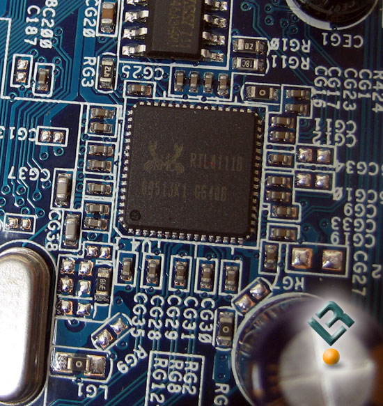
The boards sports the Realtek 8111b chip for our lan and supports PCIE Gigabit LAN at 10/100/1000 Mb/s speeds.
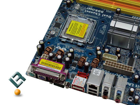
The top left of the boards reveals really the only issues I see with the layout of the board. As you can see, the 20-pin power connector is located in the middle left of this section of the board. This is really a poor placement and can cause lots of grief with cable management and cooling solutions. Why is it placed here? Late night drinking party at ASRock is all I can think of! Right next to the 20-pin is a HDD power connector that is used to add extra juice when running Crossfire. It is also not in the best spot, but is the smaller of the two issues. Lastly, the 4-pin 12v line is at the top left of the board at the edge, which is just perfect! Let me show you just a little closer look at the 20-pin placement.
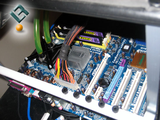
Grant it, my test bench is an open air one, but you can see how the power cable could get in the way of things.
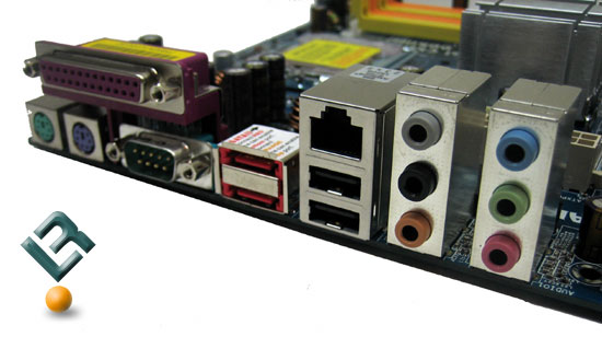
Our back I/O panel includes our typical legacy connectors like serial, parallel and PS/2 mouse and keyboard inputs. You also have 2 USB, your lan, six audio jacks, and, as the name of the board may suggest, two eSATA ports.
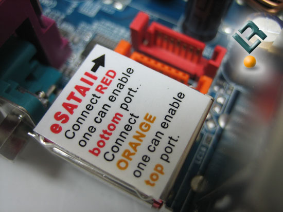
A little explanation on connecting the drives. Just behind the instructions sticker, you can see the connector on the motherboard for using the eSATA ports.
Alrighty, let’s move it along.
Comments are closed.