GIGABYTE P67A-UD4 Motherboard Performance Review
GIGABYTE P67A-UD4 Motherboard Layout
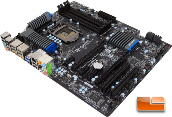
GIGABYTE has made some serious changes to the colors that they use on their motherboards. Instead of looking like a conglomeration of random colors, they have gone to an all black theme with a couple of blue highlights on the heatsinks. The all black look may have been done in the past by others, but it’s a look you just can’t go wrong with.
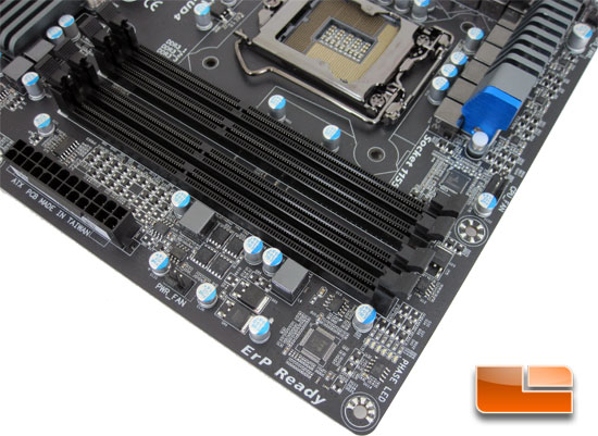
Starting out at the DIMM slots, we can see the typical four slots. The four DIMM slots will support DDR3 2133/1866/1600/1333/1066 MHz memory modules in dual channel. The black on black look makes it tough to see some of the smaller details, but halfway up the right edge of the P67A-UD4 we can see the 4pin CPU fan header, and halfway along the other edge is a 3pin power fan header. Along the right hand edge of the bottom DIMM slot is a series of Phase LED’s which will indicate the number of power phases being used by the CPU.
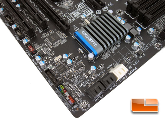
Swinging the GIGABYTE P67A-UD4 around we can catch a glimpse of the six SATA ports integrated into the board design. Four of these ports are SATA2 while two of which are SATA3 (6Gbps). Working our way up the left edge of the GIGABYTE P67A-UD4 we start with the front panel header, followed by a header for front panel USB 3.0. Next to the USB 3.0 header you can see the first of the two USB 3.0 Renesas D720200 chips that we mentioned on the front page. Just beyond the pair of solid caps are three front panel USB 2.0 headers. The first USB 2.0 header (F_USB1) along the edge will support GIGABYTE’s ON/OFF charge function when the system is in S4/S5 mode.
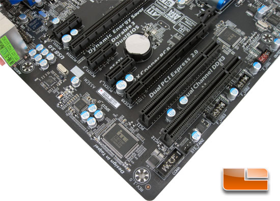
Spinning the board around once again, we can see the system fan 2 header and the serial port header. Running our eyes up the left edge of the GIGABYTE P67A-UD4 we have the iTE IT 8728F super I/O controller. Just beyond the four solid caps is the Realtek ALC 892 HD audio codec, with the Realtek 8111E Gigabit Ethernet controller beyond that. The layout of the PCIe X16 slots allows some breathing room between the cards if you are running CrossfireX or SLI. Just behind the audio jacks is the front panel audio pin out as well as the second USB 3.0 Renesas D720200 chip.
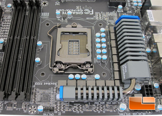
Swinging the board around we can get a good look at the LGA1155 socket and the surrounding components. Surrounding the LGA1155 socket is a handful of Japanese Solid Capacitors and Ferrite Core Chokes.

At the rear I/O panel we see the typical suspects for most boards these days. We have a single PS2 keyboard/mouse combination port with a pair of USB 2.0 ports above. Next to those we have optical and coaxial S/PDIF. There is a total of ten USB ports; the pair of blue ones in the center are the USB 3.0 ports controlled by the Renesas D720200 chip. We also have a pair of eSATA ports controlled by a Marvell 88SE9128 chip which provides data transfer up to 6Gbps and supports RAID 0 and RAID 1.
Now that we have concluded the tour around the blacked out GIGABYTE P67A-UD4, it’s time that we throw some parts on this beast and stick our heads into the BIOS and see what we have!

Comments are closed.