Corsair Carbide 400Q Silent Mid-Tower Case Review
Corsair Carbide 400Q System Build
In the build we used more modest components since this case is likely going to end up in the hands of someone looking for a best bang-for-the-buck case to maximize their spend and represents more of what the average PC user might have.
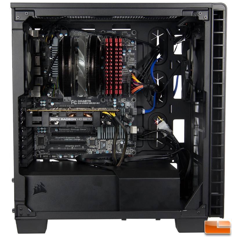
Building out a system with this case is a bit of a mixed bag. On one hand, Corsair has packed in many features that are found in high-end cases like ample cable routing cutouts with rubber grommets, plenty of space for a plethora of coolers and graphics cards, adjustable fan placement, and quality manufacturing insuring no sharp edges or burrs.
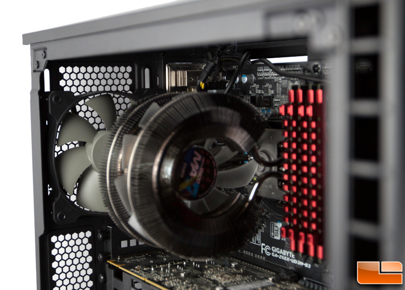
A good example is the above where I was able to slide the exhaust fan down to align with the CPU cooler and intake fan so that cool air is directed in, passed through the cooler where it picks up the hot air and passes out the exhaust fan. Simplistically of course. I had no problem with clearance with this decent sized cooler and according to Corsair, you have 170mm of clearance to play with.
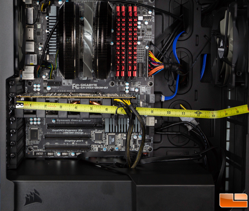
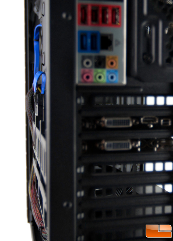
There’s plenty of room for even the longest graphics cards and room in the front for a radiator though the latter may limit the actual clearance for larger cards. The specifications call out a 370mm length clearance.
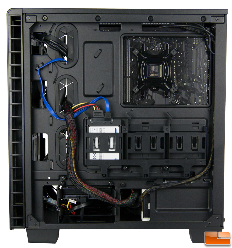
Access to the heatsink retainer behind the motherboard is not a problem at all which is a problem on some cases. So far, all of these things certainly facilitate a nice, clean build and performance. However, some of the ostensibly thoughtful features can also make the build a bit cumbersome especially for novice builders. Ill start with the 2.5 drive placement behind the motherboard tray which is something we saw on the Carbide 600C case and experienced some of the same challenges.
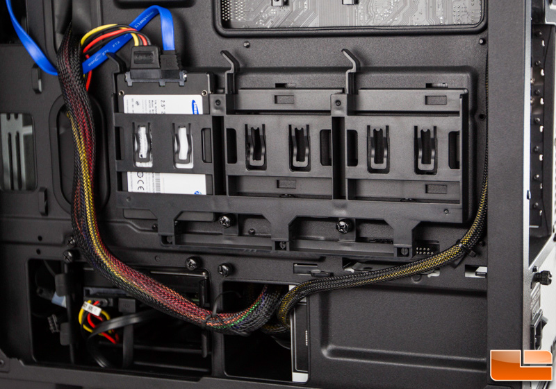
It definitely calls for straight-end SATA cables which can be problematic as many motherboards these days ship with the right-angle cables (at least on one end). The typical daisy-chain PSU SATA power cables dont really work very well either as they are designed for vertically stacked drives which has been part of case designs for many years. So, Molex to SATA adapter reserves are going to have to be called upon which adds unnecessary clutter. Not everyone has these laying around so knowing this in advance is handy not only for the preparedness but the added expense, albeit minor. I only had a few of these on hand so I limited the number of drives I loaded in the back. The two 3.5″ drives are accessed from the rear and should utilize the right-angle SATA connectors.
The plastic caddy that holds these drives is all one big piece so you cant remove unused drive slots. This is relevant because routing anything but the slimmest of cables over top of this will not allow the side panel to fit back on properly as there just isnt enough clearance. The 600C case was wider and better in this respect and each individual drive caddy can be removed. There are a good number of tie down points to ease cable routing but cable lengths are finite and there are only so many routes you can use effectively.
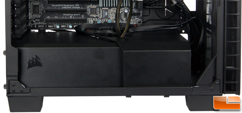
The dual piece shroud that covers the PSU and the 3.5 drive cage makes for a nice clean look and may abate some noise and heat but it definitely requires that you plan ahead in terms of your PSU cable routing. This is where novice builders will run into the most grief. This is especially true for modular PSUs as adding more cables to the unit after the shroud is in place is near impossible unless you have tiny hands and optimal plug position availability. Each piece has a hole in it for the cables to route through so you must feed all cables through here before connecting them and putting the shrouds in place. This can also get in the way of adding new drives to the 3.5 bays later on in terms of cabling. You can route some of the cables through the hole in the rear of the case instead but they would need to be long enough to reach their destination via a circuitous route.
Finally, the ‘outer’ shroud covering the drive cage butts right up against the bottom of the motherboard which was a bit of an issue for me initially because I attempted to route the USB and IO panel connectors under the motherboard as many do to mitigate clutter. The USB cables were too thick to fit through the tiny gap between the motherboard and shroud so I had to modify the route so they exited towards the front of the case. Frankly, my preference would probably be to just leave the shroud out altogether to avoid headaches later.