Asus X48 Rampage Extreme Motherboard Review
Rampage Extreme Board Images
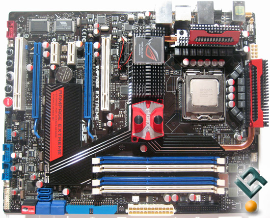
The Rampage Extreme exudes a sense of purpose just sitting on the desk before it’s even populated with components and plugged up. The sleek heatsinks look very chic yet functional, if you can consider a heatpipe array to be chic. The board itself is covered in components ranging from the 16-phase power regulation to the panel of buttons covering the bottom of the board.
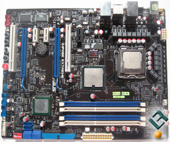
Removing the heatpipe assembly unveils even more components that are otherwise hidden. The 16-phase power regulation features two mosfets per phase. The DDR3 features two-phase power regulation while the Northbridge lucks out with three-phase power regulation.
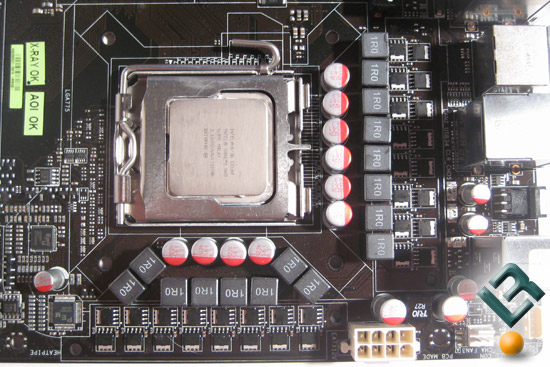
Focusing in on the CPU socket, the row of mosfets, chokes, and capacitors feeding the socket grab your eye immediately. Looking around a bit reveals the ASP0800 and ASP0801 ICs that control the PWM. The ASP0801 is a 4-phase phase controller, which means the Rampage Extreme really uses 4 real phases with each phase having 4 parallel paths for increased current handling. It’s the marketing folks that call this “16-phase” regulation but in reality it’s 4-phases. Nonetheless, it is very useful and appreciated.
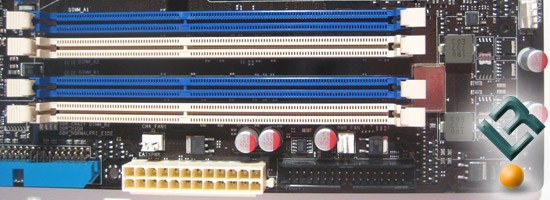
Shifting over to the DIMM area we see the two-phase DDR3 power regulation. Otherwise this section is pretty standard with the 24 pin ATX power connector and the FDD port.
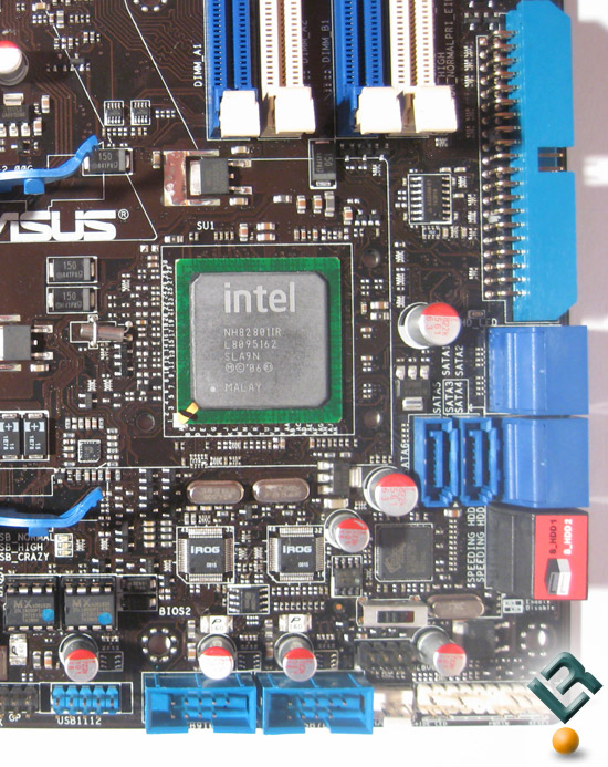
The bottom right corner of the board is quite busy. Most notable is the ICH9R southbridge. I wish they had decided to use ICH10R on the Rampage Extreme given the problems ICH9R has with SSDs; this only slightly sours this board. Since ICH9R has no PATA support, Asus has included a Marvel 88SE6121 controller with support for one eSATA port and one PATA channel for legacy support. In addition to the 6 SATA 3GB/s ports provided by ICH9R, 2 additional SATA 3GB/s ports are provided via a Silicon Image Sil5723 SATA controller with RAID 0, 1 support. Lastly there is a clear CMOS switch just in case you toast both BIOS chips.
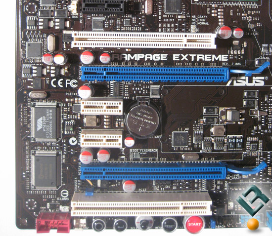
Asus didn’t go too wild with the Rampage Extreme in regards to PCIe expansion slots. There are two full-width PCIe 2.0 x16 slots, three PCIe 2.0 x1 slots, and two PCI slots. The spacing will give you a PCI slot and a PCIe x1 slot if you use CrossFire double-slot cards like the HD 4870×2. The black PCIe x1 slot is the audio slot used for the SupremeFX X-Fi discrete audio card. Two FireWire ports are provided by the VIA VT630BP controller while the Winbond W83667HG-A Super I/O controller provides legacy support for PS/2 ports and a floppy drive connector. There are two socketed BIOS chips along with some toggle switches and buttons — I’ll come back to those in a second.
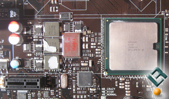
Lastly, this picture looking over the Northbridge shows three-phase power regulation to the X48 chipset. Also, near the edge of the board there are two Marvel 88E8056 PCIe Gigabit Ethernet controllers that support network teaming. The clock generator on the board is an ICS 9LPRS918JKLF for those of you using any PLL manipulation tools.
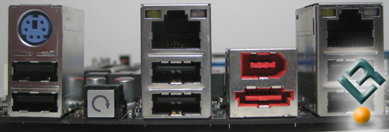
Compared to most backplates, the Asus Rampage Extreme has a rather plain setup. Two Gigabit Ethernet ports, six USB 2.0 ports, an eSATA port, and a FireWire port are all the on-board I/O ports. There is also a PS/2 keyboard port for those legacy guys out there. However, there is no PS/2 mouse port. Lastly, adding in the SupremeFX X-Fi Audio Card gives you 6 audio jacks, an S/PDIF header, and an Optical port. One last tid-bit that is seeming to become a standard, there is a CMOS reset switch that helps when you are running with a case.

Comments are closed.