Abit AT8 32X Crossfire Xpress 3200 Motherboard Review
The Layout
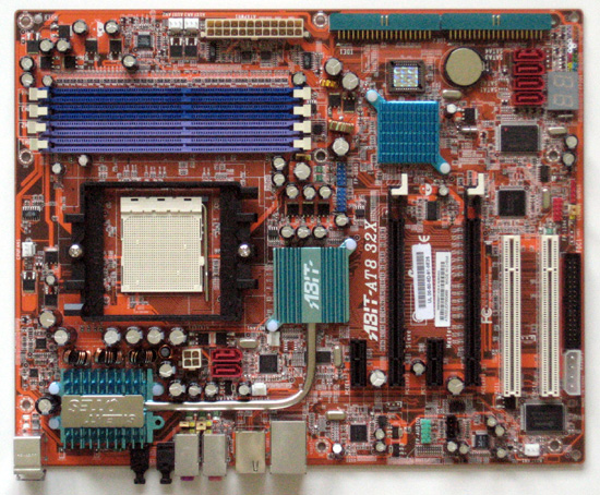
When you first look at the board, you would think you were looking at the AN8 32x as the boards are almost identical, even in their layout. There are a few differences, but unfortunately, none of the minor annoyances of the AN8 32X were fixed on the AT8 32X. Also, right off the bat I would like to say that I wish abit would have made the color of the board a little different. I am not a fan of the orange color (I prefer black PCB), but I would like to see some variations, especially between different chipsets. A red pcb for ATI and a green pcb for Nvidia would be nice… just kidding about the green! Anyways, I know it is only a preference, but I know I am not alone in having that preference. Ok, enough of the ranting, let’s look at the layout!
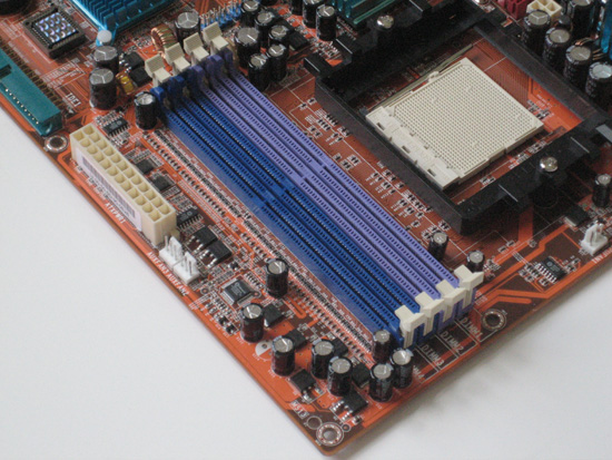
The top right of the board is the location for our dimm slots. This board has four 184-pin DIMM sockets that support dual channel configuration up to a maximum of 8GB of ram. That is alot of memory! Of course, if you are using Windows XP, you cannot utilize that much ram, let alone afford it!
We also see the CPU socket here with the standard AMD HSF mount. Nothing has changed in this area, though if you plan to go AM2 in the future, you need to do a little research to see if your HSF or water setup will fit the new CPU retention setup. In this picture alone you can see three of the six fan headers! Hook fans up to all of them and this board will levitate! it is a little ironice, that a passively cooled board would have so many fan headers!
The 24-pin power connector is also locarted here and is on the edge of the board, which is a perfect location for keeping it out of the way. There is not much more to look at here, so let’s move on!
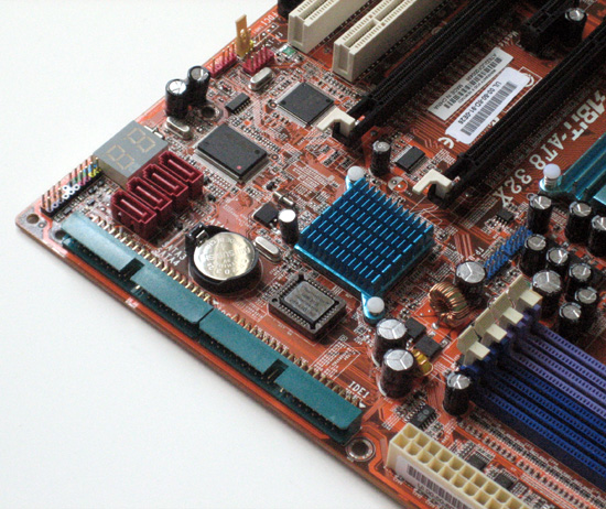
The bottom right of the board is the location of our two IDE connectors, which are also located on the side of the board. This is only a preference, but I like the location of these connectors. I would imagine that will will soon see boards preoduced with only one IDE as SATA hard drives and optical drives take over the market. IDE will go the way of the serial and parrallel ports… oh wait, there are still some boards that have those included! Who uses those things anyways! Four of the six SATA connectors are located on this part of the board as well. These connectors are powered by the chipset, support SATA2 (including RAID 0/1/0+1/5), SATA AHCI, providing native command queuing and native hot plug.
We also see the ULI1575 southbridge chipset located here, which is passively cooled with a short little heatsink. I can say that throughout the testing of this board, heat was never a problem for the north bridge of the southbridge. In fact, the heatsinks and heatpipe were just warm to the touch, even in the middle of the most extensive testing.
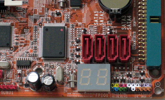
In this area of the board we also have out bios chip, the clear CMOS jumper (which we never had to use!), and the colored front panal pins. The battery is located here, and probably one of the more interesting items in the LED readout for detecting errors during operation. This is especially useful when you boot up the board, as the LED will give you a code as to why the board did not boot, should it happen to hang during the process. Here is a close up of the LED.
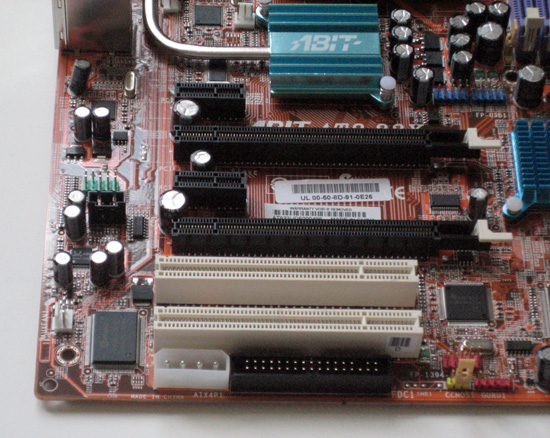
The bottom left of the board is where we find our floppy connector. This is the same location that abit used on the AN8 32X, and my opinion of this location has not changed: I hate it! I am sure most of our readers will agree that this is a poor location for this connector, and makes for sloppy cable management. Now, that being said, i do not even use a floppy any more, but there are those out there that do. Next to the ill-placed floppy connector is a 12v 4-pin molex power connection. This connection is for those that are running a dual graphics card configuration, in this case on this board, that would be an ATI Crossfire setup. I am not sure that there is a better place for this connector. I have looked at boards that have this placed rigth above the top pcie slot, and I can say that this is a much better placement.
We have a total of two pci slots on this board. The top one is unuseable if you run a graphics card in the bottom pcie slot (Crossfire). There are also two pcie x1 slots. I would certainly like to have seen abit do away with on the the pcie x1 slots so that there could be a little more room to use both pci slots. This board also has two pcie x16 slots that support dual graphic cards using ATI’s CrossFire technology. In order to run Crossfire, you must have a Crossfire edition master card if you are running the high end ATI setup. You can run two of ATI’s x1600 cards in Crossfire without a master card.
Above the pcie slots we fins the northbridge heatsink, which, like the southbridge implements a lo-profile heatsink. Unlike the southbridge though, this heatsink is connected to the heatsink on the top left of the board by a heatpipe. abit has been using this design for a while now, which is a great design for those that are setting up an quiet system with very few or no fans for cooling.
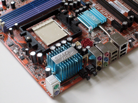
Here at the top left of the board we immediately see the big blueish heatsink that sits in the power area of the board for cooling. This is the heatsink that we mentioned the heatpipe runs to, and since it is located at the top of the board, this allows the heat to travel ina natural direction to escape out the top of a case.
The back I/O ports include the typical ps/2 connections for keyboard and mouse. There are no serial or parallel ports, which is nice to see. We have a toal of four USB2 ports here, which is a decent number for most. We have one firewire port, our audio jacks and our lan connector that is powered by the Realtek RTL8111 Gigabit Ethernet controller. The six audio jacks and two sp/dif jacks are powered by the the Realtek ALC882D high definition audio codec, which provides on board 7.1 CH HD Audio, independant multi-streaming, and supports auto jack sensing and optical S/PDIF In/Out. Onboard sound certainly has come a long way!
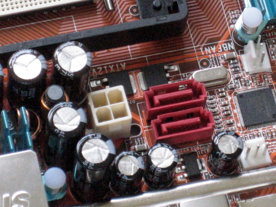
There are two more SATA connectors located here. These SATA connections are powered by the Silicon Image Sil3132 PCIE SATA 3Gb/s RAID controller. I am not to fond of the location of these connectors, but I also do not use them, so they are of no consequence to me. Right next to the SATA connectors is the 4-pin 12v connector. This is tucked in there pretty tight, and if you have big hands or fat fingers, it could be difficult to remove the connector when needed. Here is a little closer shot of the placement.
Ok, so that is the board, let’s look at the bundle that comes with it.
Comments are closed.