The Intel P35 Chipset Motherboard Round-Up – Abit, ASUS, Foxconn
The Abit IP35 Pro Specs and Layout

The first board we will look at will be the Abit P35 Pro. Abit has a reputation of being a great enthusiast product, so their marketing of a board that goes off limits and to the wild side fits. Let’s look at the specs first:
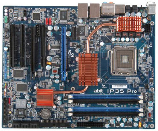
A quick glance at the board reveals it clean layout. It also reveals maybe a thing or two that could cause you to turn your head and look twice at. But we will save that for now, and take it as it comes in the closer look at the board.
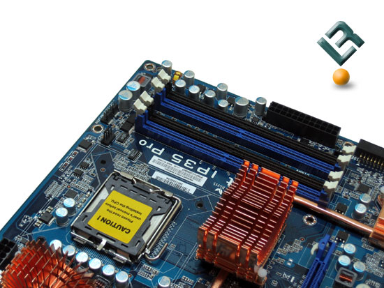
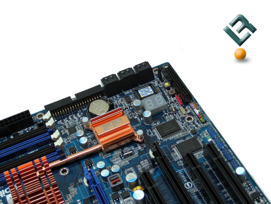
The top right of the board is where we find our typical placement of the ddr slots. This board (and all P35 boards) supports up to 8GB of ddrII memory in 533/667/ and 800 ddr speeds. We also see our 24-pin power connector here, as well as the beefy copper heatsink on the northbridge.
The bottom right of the board give us our IDE connector, which is on the edge of the board, right where it should be. Just underneath that is our six SATA connectors. These are powered by the Intel ICH9R chipset, and provide the ability to run RAID 0/1/5/10. The placement of these connectors will likely cause some to rejoice and others to frown, as it could be a little difficult to connect the SATA drives to these connectors with their sideways mounting. Infact, with some cases I have had, it may be almost impossible. You can also see the copper heatsink on the southbridge here.
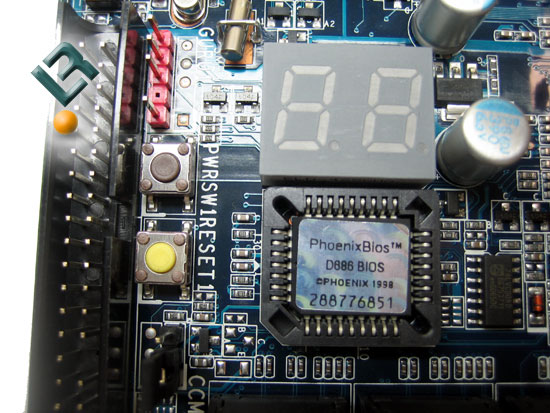
We also find the BIOS chip on this part of the board. Just above that we have and LED display that will tell us all we need to know as the board boots. If there is a problem, the LED is sippose to give you the code where it is getting hung up, which should be a great help for troubleshooting. Next to the LED and BIOS chip we have two buttonms that I just love! This is a power switch and a reset button. These is a great asset for those who do not set their board up in a conventional method (i.e. – in a case).
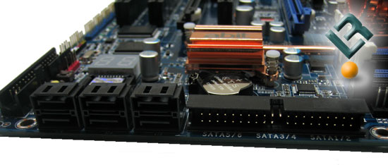
Here we have just a little closer look at the SATA and IDE connectors.
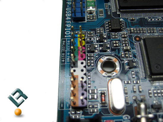
The front panal connector pins are conveniently colored for ease of installation.
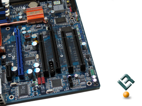
The bottom right of the board gives us our add-on card slots. This board has three legacy PCI slots, one x1 PCI-E slot, and two x16 PCI-E slots, one of which is limited to x4 bandwidth. This may or may not be an issue to you, but your bandwidth is limited when using this slot. One other concern may be the extra power connector that is placed just between the top PCI and the bottom PCI-E slots. This could cause some wiring problems if you are using all of these slots on the board.
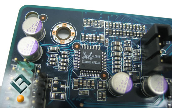
We find our audio chip here as well. This board has the Realtek ALC888 chip, which provides 7.1 channel hi-def sound, and allows for auto-jack sensing.
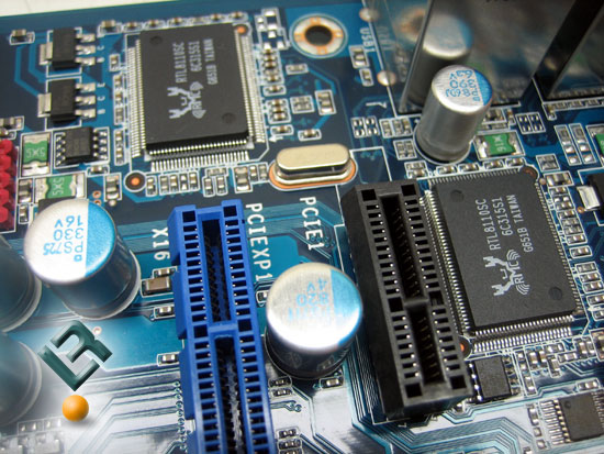
The board also sports dual gigabit lan that is powered by two Realtek 8110SC chips.
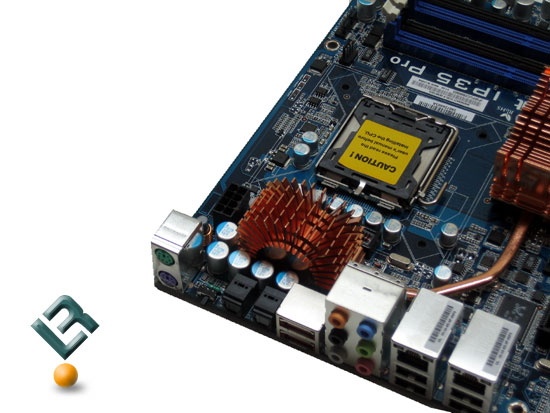
The top left of the board is wehre we find our CPU socket. The P35 chipset supports 1333fsb processors, helping future-proof this board a little bit. We also see another copper heatsink that is linked with the heatpipe on the board. The 8-pin 12v connector is right at the top of the board, in a perfect position.
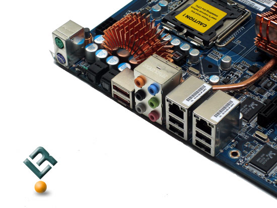
The back I/O ports give up our legacy PS/2 keyboard and mouse connectors, as well as SPDIF in and out jacks. We also have two eSATA connections here, which are powered by the JMICRON JMB363 controller. Our six audio jacks are here, as well as four USB2 connectors and our dual giga-lan ports as well as a Clr CMOS button (I like this!).
Comments are closed.