GIGABYTE GA-X99-Gaming G1 WiFi Motherboard Review
GIGABYTE X99-Gaming G1 WiFi Motherboard Layout
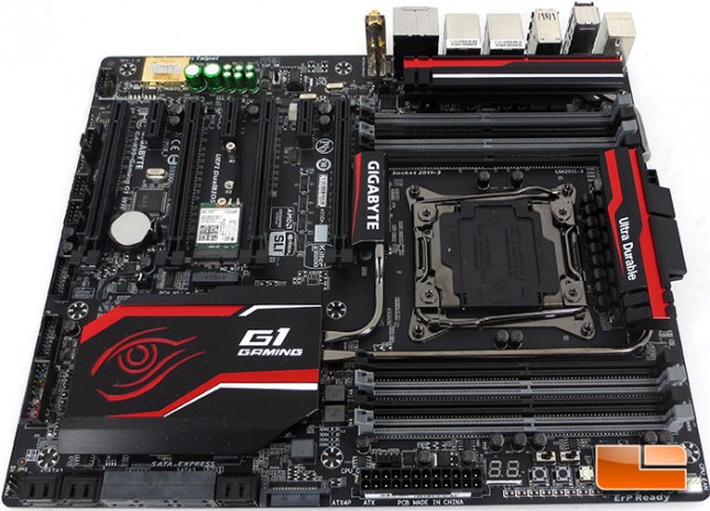
The GIGABYTE X99-Gaming G1 WiFi is a nice looking board. While looks alone wont sell me on the X99-Gaming G1 WiFi, it certainly doesn’t hurt the case. The blacked out look has become pretty common, but the GIGABYTE X99-Gaming G1 WiFi is accented with grey DIMM slots and red and white on the heat sink assemblies. Definitely sharp looking and would look great in any case.
The GIGABYTE X99-Gaming G1 WiFi is capable of running eight DDR4 DIMMs in a quad channel configuration. The X99-Gaming G1 WiFi will support up to 64GB of memory at frequencies as high as 3000MHz (O.C.).
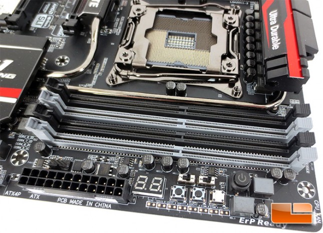
Taking a little bit of a closer look at the corner of the GIGABYTE X99-Gaming G1 WiFi motherboard, there are a number of features packed in here. At the very corner of the X99-Gaming G1 WiFi is the 4pin CPU Fan header. Along the edge of the X99-Gaming G1 WiFi PCB is a handful of voltage check points with a set of three buttons just above there. The three buttons (2 black, 1 white) include a reset switch (RST_SW, white), CMOS switch (center black), and the DTB (Direct to BIOS, left black). Above the three buttons there are a pair of switches, the left switch will toggle the X99-Gaming G1 WiFi between single BIOS and Dual BIOS mode, the right switch will toggle the board between the two different BIOS chips. To the Right of the switches is the final button, the onboard power button. To the left of the switches is the DeBug LEG, 24pin motherboard power, and a 4pin optional CPU fan header.
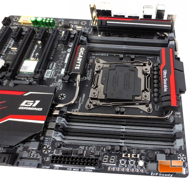
Rotating the GIGABYTE X99-Gaming G1 WiFi motherboard around, the most noticeable item here is the G1 Gaming heat sink on the Intel X99 chipset. Surrounding the heat sink there are a number of important features too. Starting where I left off above, next to the 24 pin motherboard power is a SATA power plug, though it actually doesn’t have anything to do with the SATA ports next to it. The SATA power plug supplies additional power to the PCIe X16 slots, which can come in handy while overclocking multiple graphics cards. Continuing down the edge of the PCB there is a total of 10 SATA III 6 Gbps ports, and a 4pin chassis fan header. Working our way up the edge of the X99-Gaming G1 WiFi, there is the front panel pin out, a pair if internal SuperSpeed USB 3.0 headers, and the first of two internal USB 2.0 headers.
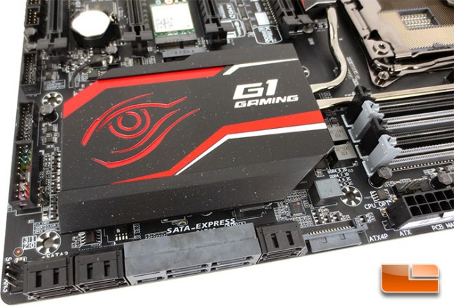
Continuing down the edge of the GIGABYTE X99-Gaming G1 WiFi there is the second of the internal USB 2.0 headers followed by a 4pin system fan header, Thunderbolt header, another 4pin system fan header, and finally the front panel audio header. Rounding the corner of the GIGABYTE X99-Gaming G1 WiFi we are presented with the Creative Sound Core 3D chipset and all of the Nichicon high end audio capacitors. A little bit further down the edge of the board there is the interchangeable OP-AMP that can help fine tune your audio experience.
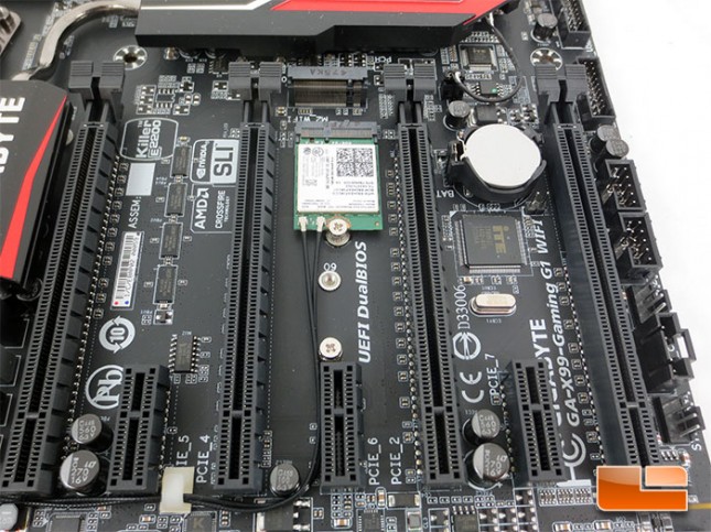
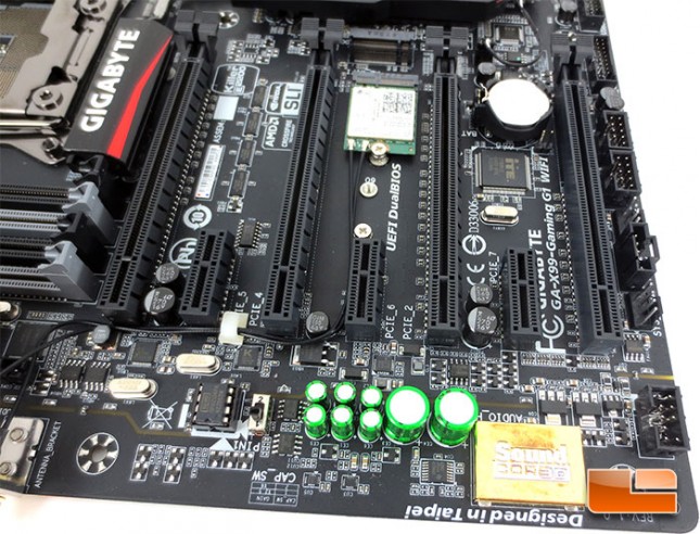
The GIGABYTE X99-Gaming G1 WiFi features four PCIe X16 slots that are all PCIe Gen 3.0. PCIE_1 and PCIE_2 will both operate at x16 while PCIE_3 and PCIE_4 will operate at x8 modes. Though PCIE_4 and PCIE_1 share bandwidth and will both operate at x8 if PCIE_4 is populated. Between each of the PCIe X16 slots there is a PCIe x1 slot that conforms to PCIe Gen 2.0. Tucked in between PCIE_2 and PCIE_3 is a pair of M.2 slots. The lower M.2 slot comes populated with a Wi-Fi 802.11 a/b/g/n/ac, supporting 2.4/5 GHz Dual-Band wireless card. The upper slot is waiting to be populated by your choice of M.2 SSD’s.
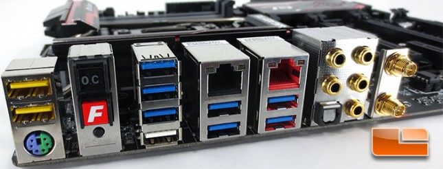
The GIGABYTE X99-Gaming G1 WiFi I/O panel is packed with features, for starters there a total of 10 USB ports. Of the ten USB ports on the back panel, eight of them are SuperSpeed USB 3.0 while the remaining pair are USB 2.0. GIGABYTE employs a pair of Renesas uPD720210 USB 3.0 Hubs to split the native USB 3.0 ports into the eight. The X99-Gaming G1 WiFi is also equipped with a pair of Gigabit Ethernet jacks, one is controlled by a Qualcomm Atheros Killer E2201 chip while the other is a Intel Gigabit Ethernet controller. Along the right side the pair of WiFi antenna connectors can be seen. Beneath the pair of USB 2.0 ports, there is a PS/2 port that can be used by either a mouse or keyboard. There is also a series of buttons hanging out back here, the O.C. button is pretty self explanatory as it will overclock the CPU automatically for you. The red ‘F’ button is the fast boot button I talked about earlier. Below the Fast Boot button is the ever important CMOS reset button should you need to clear your system settings. Last, but far from least is the set of five 3.5mm audio jacks that are driven by the Creative Sound Core 3D high definition audio controller.
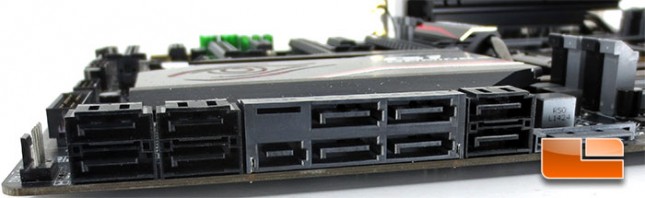
The GIGABYTE X99-Gaming G1 WiFi motherboard packs in 10 SATA III 6Gbps ports on it, a pair of which can be tied up while using SATA Express.