Building Your Own Computer (DIY) Guide
Installing The Memory and Motherboard
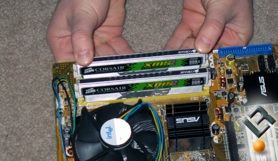
With the memory be sure to open the white levers on each side of the memory slots and to line up the notch in the memory module with the notch in the board. Then gently press each memory module into the color matched slots (yellow on this board) till they click into place. The white levers that were open should now be closed locking the memory into place. Not too hard now is it?
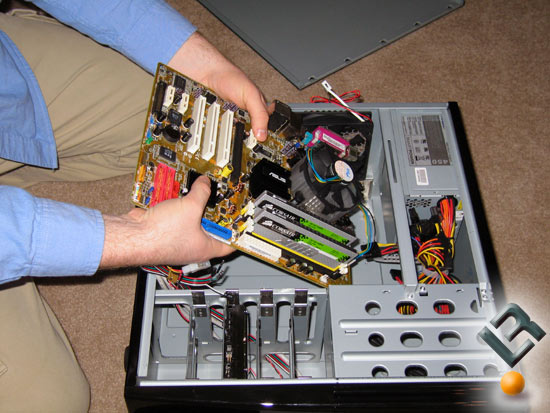
Now we have the motherboard ready to install into the Antec Sonata II case. Grabbing the case that we started with we have to do some changes to get our board to fit correctly. The case comes with extra motherboard stand offs (the brass studs) as not all of them have been installed. Since motherboards come in different shapes and sizes they leave some out. If you don’t know which ones to install you can place the board in the system and figure out which ones need to be installed.
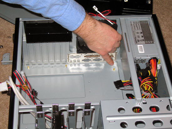
With the motherboard stand offs installed we have to remove the back panel that comes with the Antec Sonata II and install the one that came with the ASUS motherboard bundle. Gently press out the the old plate by firmly pushing on it from the outside of the case torwards the inside till it pops out. Below shows what it will look like with the plate removed. The new ASUS plate (top) and the old Antec plate (bottom) are very different and if you don’t use the correct one the motherboard won’t fit in the case correctly. Install the new plate by pushing it into the housing from the inside out.
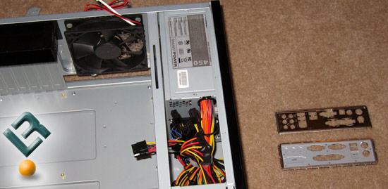
This back panel is an I/O shield that is used to block radio frequency transmissions, necessary to pass emissions (EMI) certification testing, protect internal components from dust and foreign objects, and promote correct airflow within the chassis. It is needed so don’t leave it out as some people do without knowing. After making sure the new plate is all the way pressed in it should look like this:
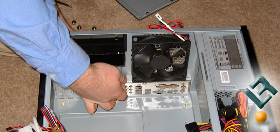
With the motherboard studs installed and the back plate switched out we are ready to install the motherboard. Getting the motherboard into the case it tricky and the board will need to be rotated for it to fit. Do not get frustrated and try forcing the board into the case. Motherboards can flex, but are not designed for this and will break. I know an RMA will not cover a cracked board! Note that the black fan duct in the above picture should be removed during this step. This is easily done by sliding the housing up to the power supply and then pulling it away from the back of the case.
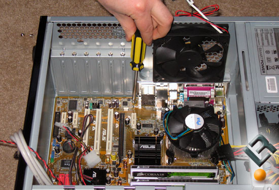
After the motherboard is lowered into the case and lined up with the back panel you are ready to screw it down. When tighting the motherboard down one should apply some force, but no more than a wrist can apply. If you start to really twist then you are using too much force. Just snug them down and you will be fine. It’s not a lug nut on your car so don’t get carried away!
On the ASUS P5LD2 motherboard that we used in this build has seven screws that seven screws that should be used and their locations are shown below.
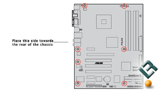
After all the screws are inserted and tightened the motherboard is installed! Now let’s put in the video card.
Comments are closed.